
In the previous part of this series I cut open an HDMI cable between a Blackmagic Design ATEM Mini and a Pocket 4k camera to attempt to figure out how the ATEM Mini can control the camera over the HDMI cable only.
While reverse-engineering that I looked into the CEC lines and was unable to get the DDC data at the same time because cutting up a HDMI cable is not a reliable way to probe data. The first thing I did was make a neat PCB for debugging this further.

This is a very simple board that has two HDMI connectors with all the high speed pairs connected straight accross and all the slow speed signals broken out to two pin headers. One 7-pin header gives probing access to all the pairs, voltages and ground and a 2x6-pin header allows breaking the connection between the two HDMI ports for any of the data signals by removing the jumpers.

With this setup I'm able to dump all the traffic I'm interested in. Plugging in the camera shows up as a glitch in the HPD line, then the SDA/SCL lines are busy for a bit communicating the EDID for the "display" implemented in the ATEM Mini HDMI input. Then the CEC line starts showing activity with the port number the camera is plugged into and some vendor specific commands.
Looking back at my previous post after I've figured out more of this and after reading parts of the HDMI and EDID specs it turned out that I already had all the data, I just didn't recognize it yet.
On my initial look at the CEC data I did not know which bytes are transmitted by which device. With just removing the CEC jumper from by board it became quite visible which data was sent by the camera and even without the CEC line being connected to the ATEM Mini at all. Also I noticed that the camera still knew what camera number it had. I initially assumed the first bytes containing the camera number were coming from the ATEM side. Since that connection is severed it must be getting this data from the EDID blob.
The EDID specifications
PulseView only shows annotations for half the EDID blob it has received. So I turned to the suprisingly great EDID Wikipedia page which documents all the bytes. My first try to figure things out whas the parse-edid command on Linux from the read-edid package. This does parse all the monitor and resolution data I don't want but does not seem to decode all of it. I pasted the EDID blob in my hex dump slicer and started annotating the bytes according to the Wikipedia page.

The annotated part covers the initial 128 bytes of the EDID blob with the basic monitor information. The num_exts byte here is set to 0x01 so immediately following it is more data, in this case a CEA-861 extension block. This block can contain more detailed resolution info (and more importantly, resolutions for more modern monitors). It also has space for custom data blocks. The first blocks are the well documented Video block, Audio block and Speaker block. The fourth block that exists is the Vendor block.
I made a wrong assumption here. I thought since this is a vendor block it would be a block with undefined data from BlackMagic Design. This block also contains the only byte that changes between the 4 ports of the ATEM Mini. The fourth byte of this block was 0x10, 0x20, 0x30 and 0x40 for the four ports which confused me even further, why is this using the high four bits.
After having another coffee and reading the Wikipedia page on EDID a bit further I found out that the first three bytes of the vendor block are the vendor identification which makes sense if you can have multiple of these vendor blocks. To my suprise the example value of a vendor id is 0x000c03 which is in my packet dump.
Turns out I was reverse engineering the HDMI 1.4 specification here. It's even possible to just download this specification! The most useful part of that PDF is this:

The changing 4 bits is the one marked A in this table. And... the A,B,C,D fields are for setting the CEC physical address for the device connected to that port.
So suprisingly so far everything here is just in-spec and documented and I now learned more on how CEC works. The camera reads the EDID block to know the output timings and also reads the CEC physical address from the ATEM. In my case the port number wasn't 0x40, it was the 0x40 0x00 which translates to CEC address 4.0.0.0
So if I want to remotely control my camera I need to do EDID emulation and insert this data block if the upsteam device did not already set it.
The CEC part
So lets have a look at the CEC communication after the EDID exchange has happened. First quickly after connecting there's two very short bursts of CEC data. PulseView decodes this as CEC pings so I will ignore those for now. This is an export of the rest of the CEC data in this recording:
8185-700390 CEC: Frames: 1f:84:20:00
712370-745164 CEC: Frames: 1f:a0:7c:2e:0d:01:01
748596-757793 CEC: Frames: 01:01
761361-775144 CEC: Frames: 10:02:01
778761-802480 CEC: Frames: 01:50:3c:00:00
806749-864354 CEC: Frames: 01:70:25:70:20:43:41:4d:20:25:69:00
868623-906865 CEC: Frames: 0f:a0:7c:2e:0d:02:02:10
911133-939694 CEC: Frames: 01:68:70:74:73:00
943963-962842 CEC: Frames: 01:65:32:00
The CEC protocol uses addressing with 4 bits for everything. In my packet dump for this trace the camera was connected to port 2.0.0.0 of the ATEM. The first byte of the CEC frame is also address info, but this is the logical address instead of the physical address. This is split in 4 bits for the sender and 4 bits for the receiver. Address 0 is always the CEC root which is the ATEM and Address F is the broadcast address. The camera uses address 1 for its communication. The second byte if the packet is the CEC opcode.
The first packet the camera sends is opcode 0x84. This is a mandatory packet that is broadcasted from the device that's connected to tell the CEC network about the mapping between the physical address and logical address. In this case logical device 0x1 is broadcasting that the physical address is 0x2000 which is 2.0.0.0.
The second packet is opcode 0xa0 which is "Vendor Command With ID". Now I've entered the reverse engineering area again. The next 3 bytes is 0x7c 0x2e 0x0d which corresponds to the OID for BlackMagic Design and the vendor data is 0x01 0x01. After this packet has been sent the communication starts breaking the CEC specification and is now just sending BMD specific data. All the data PulseView is trying to decipher from the bytes are just red herrings.
Emulating the ATEM
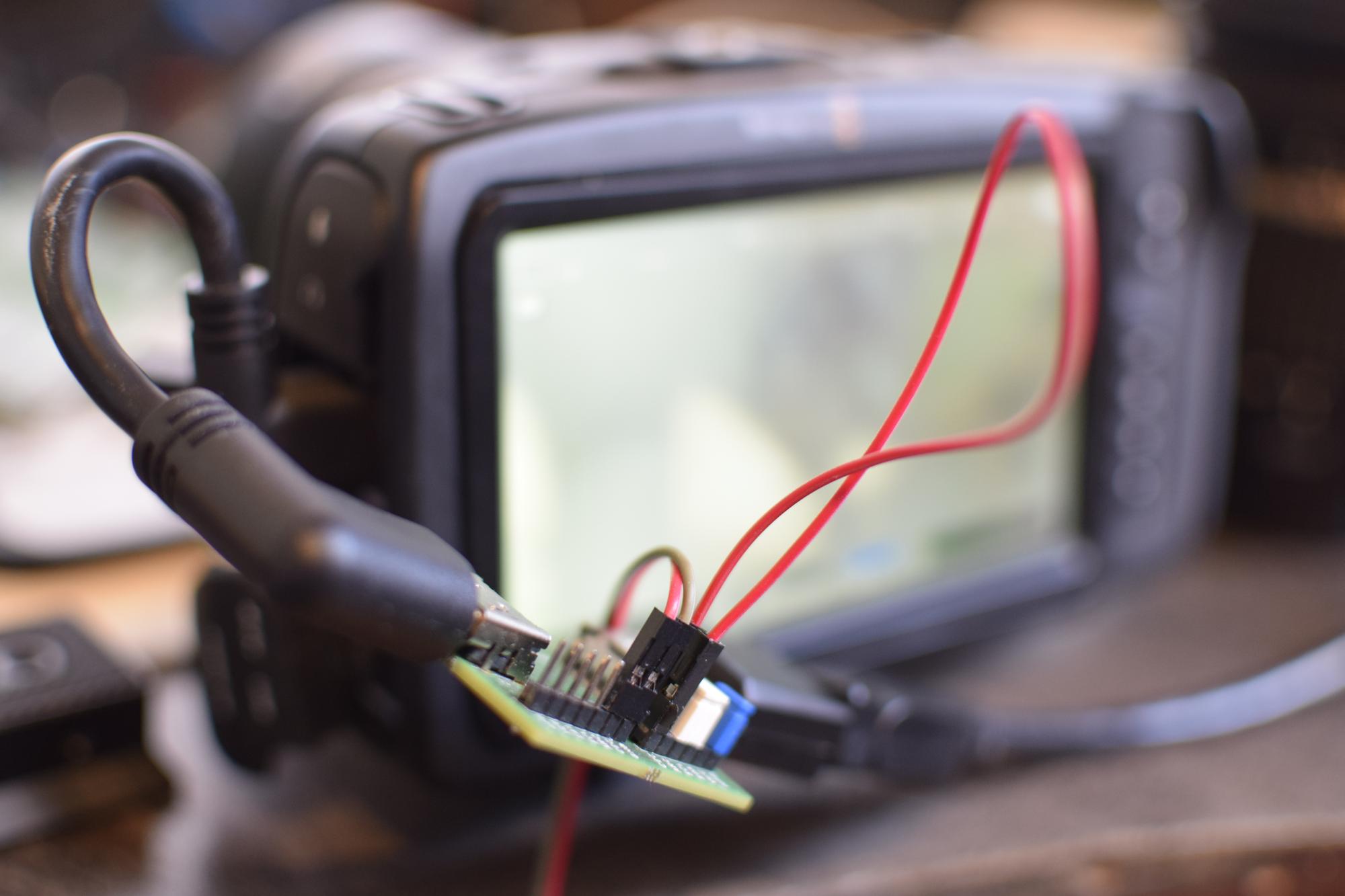
So now the basics of the communication are known the next part is emulating an EDID and seeing what happens on the CEC line to get more information. For this I'm using a Raspberry Pi Pico hooked up to my HDMI passthrough board.
I removed all the jumpers from the passthrough board to isolate the slow signals in the HDMI connection and hooked them all up to the Pico. On the initial tests I could not get any signals from the camera this way, I was expecting just pulling the hot-plug-detect pin high would be enough to start the HDMI connection. It turns out that I need to have a monitor connected to the high speed pairs to make the camera happy.
The first thing the camera does is reading the EDID so I started with implementing EDID emulation. For this the Pico should act as an I2C slave which is suprisingly undocumented in the SDK manual. The only thing the manual says about it is using the i2c_set_slave_mode(i2c0, true, 0x50) command to put the hardware in the right mode. The rest is undocumented and requires poking registers outside of the SDK for now, hopefully that will get fixed in the future. With this I implemented an I2C device that responds on address 0x50 and has a block of 256 bytes of data. This just contains a copy of the EDID of one of the ATEM ports for now.
The harder part is doing CEC on the Pico. So far it seems like nobody has made a library for this and due to the existence of CEC on the Raspberry Pi SBCs it makes searching pretty hard. In theory it should be possible to implement this using a PIO block to handle the bitbanging part. For now I'm just using one of the cores to bitbang the protocol.
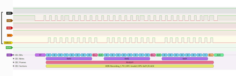
This implementation just supports receiving CEC data and sending the ACK back to make the camera continue sending data. The debug pin in this trace is used to debug the sample point and packet detection in my code. The bit is sampled on the rising edge and the start of a bit is on the falling edge. During the ACK bit the gpio on the Pico is switched to output to drive the CEC line low.
The packet shown above is the first packet the camera sends after sending the BMD vendor comand. When connected to the ATEM the next thing that happens is that the ATEM sends a few unknown bytes back. If I don't reply on this packet the camera will restart the whole CEC session after 1.5 seconds by broadcasting it's physical address again.
So the first thing I tried sending back to the camera is CEC operation 0x9F. This is requesting the CEC version of the device. It turns out the CEC implementation in Blackmagic Design cameras is quite out of spec. It acks my data and then proceeds to never respond to CEC data again. Technically following the CEC 1.4 specification it was already out-of-spec because of sending a vendor command without first requesting the vendor id of the device it's connected to.
So since it's no longer really speaking CEC at this point I started looking into replaying some of the messages I had captured to see how the camera behaves. There's a few things that are sent from the ATEM to the camera directly after startup that don't seem to be correlated to any camera config.
The first thing is operation 0x01 directly after sending the vendor command. Then operation 0x50 and 0x70 and lastly another full CEC vendor command but to the broadcast address instead. After some testing it looks like operation 0x01 is required to make the camera "accept" the connection. It stops the restart of the session after 1.5 seconds. I can't figure out what operation 50 and 70 do but leaving those out does not seem to change anything.
The broadcasted vendor command is the tally data which I also can ignore for now. The next command I sent is 0x01 0x52 0x00 which sets the gain of the camera. By sending this directly after receiving the 0x02 the camera sends on startup the gain on the camera display changes!
Figuring out more opcodes
Now I have a somewhat working setup I tried once again changing settings in Atem software control and observing the CEC data. With this process I figured out 35 opcodes.
The reference document for this is "Blackmagic Camera Control Developer Guide". This document does not have any information on the HDMI protocol but it does document how to control the camera over SDI. The most important thing is the list of parameters that can be sent to the device. I was hoping the bytes in the HDMI protocol relate to information in that document in any way but it seems not.
It looks like the developers at Blackmagic Design created a completely new protocol for the CEC communication to deal with the update speed. The CEC bus is roughly 300 baud and the commands that are sent over the very fast SDI interface are just too long to have reasonable response times. The gain command in the CEC protocol has only a single data byte and that takes nearly a tenth of a second to transmit, the same command over SDI is 8 bytes long already.
While dumping the CEC traffic I also noticed some commands are significantly longer. An int16 value being 10 bytes long in this case. All these long commands for various features are also all on opcode 0x04. After looking at the similarities and differences on these long packets I noticed that this is just a passthrough command for the older SDI commands.
# Parameter 0.4 on HDMI (Aperture ordinal)
01:04:81:03:ff:00:04:02:00:10:00

# Parameter 0.4 on SDI
03:05:00:00:00:04:02:10:00
The byes are in different order and there's some extra static bytes for some reason but it does seem to map to the documentation. Sending one of these packets takes roughly 300ms, which is why this is not used for parameters you control using sliders or wheels in the control interface.
The whole list of parameters I found is:
05 00 00 00 00 00 00 00 00 # Reset lift
06 00 00 00 00 00 00 00 00 # Reset gamma
07 00 00 00 00 00 00 00 00 # Reset gain
0D xx xx                   # Lift R
0E xx xx                   # Gamma R
0F xx xx                   # Gain R
11 xx xx                   # Lift G
12 xx xx                   # Gamma G
13 xx xx                   # Gain G
15 xx xx                   # Lift B
16 xx xx                   # Gamma B
17 xx xx                   # Gain B
19 xx                      # Lift W
1A xx                      # Gamma W
1B xx                      # Gain W
1D xx xx                   # Hue
1E xx xx                   # Saturation
1F xx xx                   # Pivot
20 xx xx                   # Contrast
21 xx xx                   # Luma mix
33 1E                      # Show bars
33 00                      # Hide bars
40 xx xx                   # Absolute focus (ID 0.0)
41 xx xx                   # Focus distance
42 XX XX                   # Iris (ID 0.2)
43                         # Trigger instant auto-iris (ID 0.5)
44 XX XX                   # Set absolute zoom in mm (ID 0.7)
46 xx xx                   # Zoom
47                         # Trigger autofocus
52 xx                      # Gain
54 xx                      # Temperature
55 xx                      # Tint
56                         # Trigger AWB (ID 1.3)
57 xx xx xx xx             # Shutter (ID 1.5)
58 xx                      # Detail 0, 1, 2, 3
The exact encoding for the bytes still need to be figured out but it seems to mostly follow the encoding described in the SDI command manual.
All that's left is implementing a nice API for this in the Pi Pico to automate camera control :)