
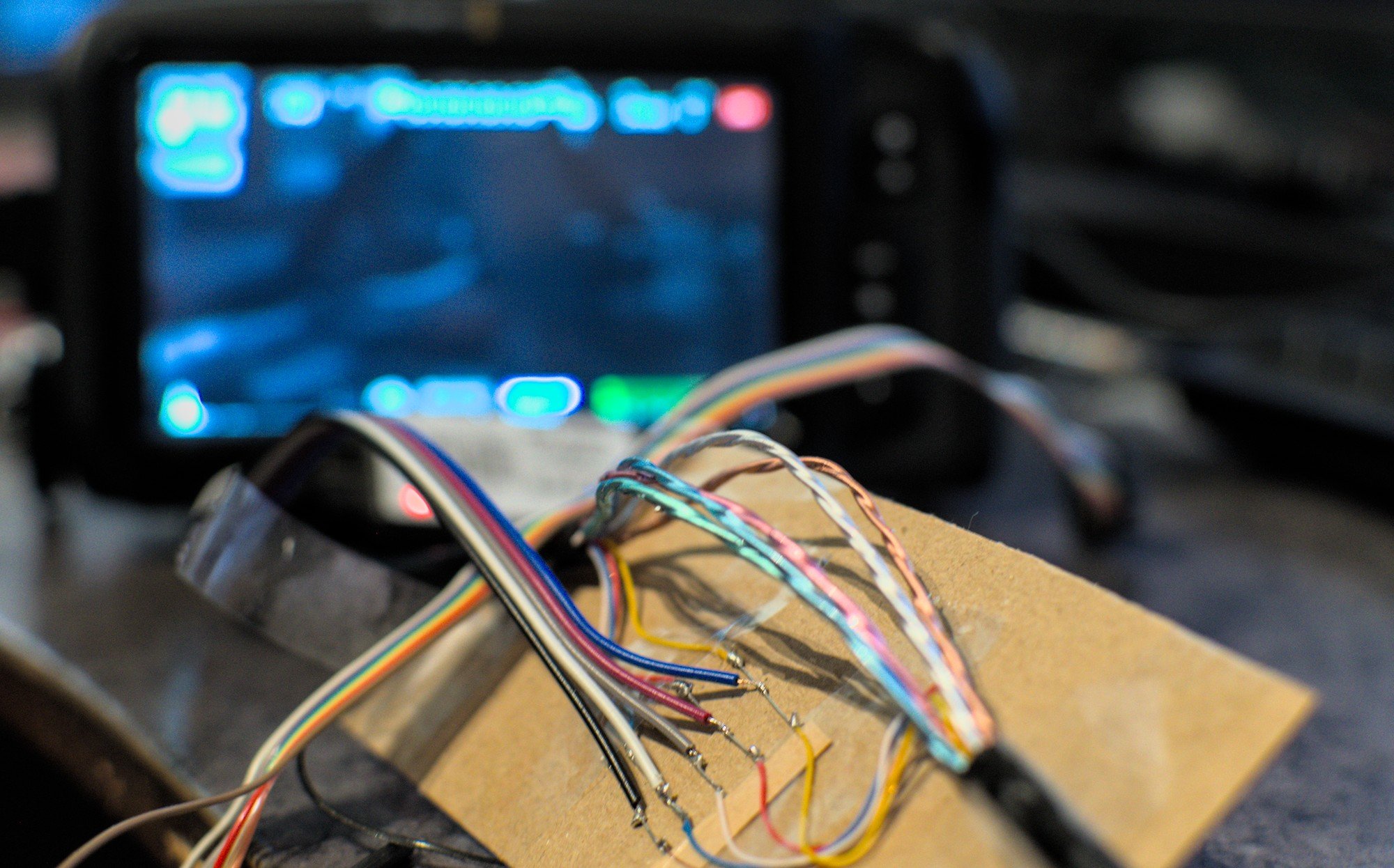
I have a Blackmagic Design 4k camera here (the bmpcc4k) and it has an interesting feature where you can control camera settings when hooking the hdmi cable from the camera to a BMD Atem mini series video switcher. It allows controlling a few settings that are not accessible in the camera settings itself like the values of the primary color corrector.
This is the exact same thing that their more expensive cameras for studios can do by hooking up a SDI (video over coax) cable to it and hooking it into a more expensive ATEM switcher.
The camera also has Bluetooth control which allows you to change some basic settings like resolution, audio settings and lens control. I have been able to use this but unfortunately I ran into a hardware defect where the touchscreen on the camera just stops working. At this point I did not have bluetooth switched on so I cannot even change my camera settings through that anymore. While this is a defect in the camera looking at the forums BMD did not really want to help with getting this fixed unless I pay a lot to get this fixed.
The alternative is figuring out how the HDMI control works, figuring out how much more is possible over that protocol and try to enable bluetooth through that.
Guesses
So the camera is controlled over the same HDMI connection that's used to feed the signal to the atem switcher. This works even with the cheapest cables I have and cable manufacturers love reducing the amount of wires in their cables. This doesn't leave a lot of option where that data can be. All the high speed data pairs in HDMI are directional and are going in the camera->switcher direction so it's not using anything complicated inside the HDMI frame to get data across. Looking at some pinouts this basically only leaves the CEC and DDC stuff.
DDC is the display data channel, it's an i2c bus that's used to query the information about the monitor that the cable is plugged in to. This exact same system is present in VGA, DVI, Displayport and HDMI. I guess the standard was good enough that it was just copied over to every newer one :)
Sniffing the DDC traffic
Messing with the DDC bus is usually pretty simple. On linux you can load the i2c-dev module and that will expose the DDC connections on all video outputs as /dev/i2c-* nodes. If I have my computer hooked into the HDMI input of an ATEM switcher I can dump the edid data over the bus using i2cdump for example:
# Bus 1 is my HDMI connector, 0x50 is the i2c address for the EDID eeprom
$ i2cdump -y 1 0x50
No size specified (using byte-data access)
     0  1  2  3  4  5  6  7  8  9  a  b  c  d  e  f    0123456789abcdef
00: 00 ff ff ff ff ff ff 00 23 01 00 00 01 00 00 00    ........#?..?...
10: 26 10 01 03 80 47 28 96 0a da ff a3 58 4a a2 29    &????G(???.?XJ?)
20: 17 49 4b 00 00 00 01 01 01 01 01 01 01 01 01 01    ?IK...??????????
30: 01 01 01 01 01 01 02 3a 80 18 71 38 2d 40 58 2c    ???????:??q8-@X,
40: 45 00 c4 8e 21 00 00 1e 02 3a 80 d0 72 38 2d 40    E.??!..??:??r8-@
50: 58 2c 45 00 c4 8e 21 00 00 1e 00 00 00 fc 00 42    X,E.??!..?...?.B
60: 4d 44 20 48 44 4d 49 0a 20 20 20 20 00 00 00 fd    MD HDMI?    ...?
70: 00 32 3c 1f 44 08 00 0a 20 20 20 20 20 20 01 f7    .2<?D?.?      ??
80: 02 03 1f 54 49 85 84 94 93 a0 a1 a2 9f 90 23 09    ???TI?????????#?
90: 04 07 83 01 00 00 68 03 0c 00 10 00 00 1e 00 01    ????..h??.?..?.?
a0: 1d 00 72 51 d0 1e 20 6e 28 55 00 c4 8e 21 00 00    ?.rQ?? n(U.??!..
b0: 1e 01 1d 00 bc 52 d0 1e 20 b8 28 55 40 c4 8e 21    ???.?R?? ?(U@??!
c0: 00 00 1e 00 00 00 00 00 00 00 00 00 00 00 00 00    ..?.............
d0: 00 00 00 00 00 00 00 00 00 00 00 00 00 00 00 00    ................
e0: 00 00 00 00 00 00 00 00 00 00 00 00 00 00 00 00    ................
f0: 00 00 00 00 00 00 00 00 00 00 00 00 00 00 00 f2    ...............?
Doing the same for the camera is a lot harder though. Since the direction for that is reversed the computer has to be i2c slave on the hdmi connector instead which is not something that's just easily doable.
The other option is just splicing into the HDMI cable and finding the right wires. So that's exactly what I did.
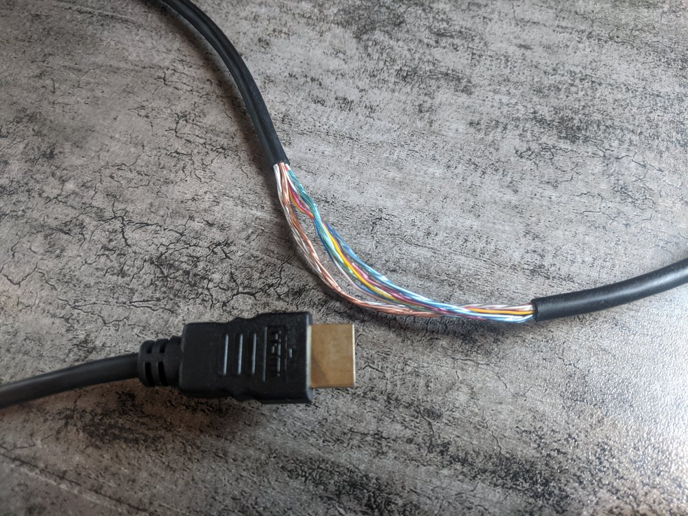
After removing a part of the outer isolation and shielding from an HDMI cable it looks like there are a bunch of high speed differential pairs with individual shielding. Those are not interesting for the data I'm looking for, they will be the clock pairs and a pair for red, green and blue pixels (or YUV in some modes). Besides those pairs there are 4 wires left over and a ground wire.
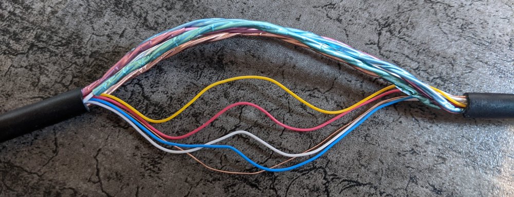
DDC needs two wires to work, SDA and SCL for data and clock, and it needs the ground wire. The other two wires might be the +5V wire that was originally intended to power the EDID chip when the monitor is off. And a wire for hotplug detection of the connector. Since I don't care that much for the signal integrity of the cable, and these wires carry slow signals. I just decided to cut them and splice in some leftover resistor leads to heave points to attach probes to.
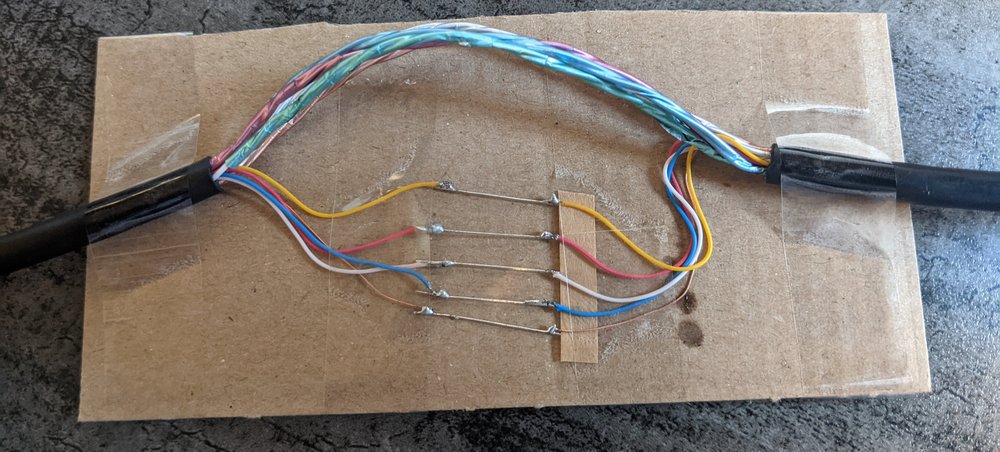
Then I just connected probes to these wires and hooked it up to a CWAV USBee AX 8 channel logic analyzer. With that connected and the wire colors correctly labeled I ran a 10 second dump in the sigrok pulseview software and plugged in the camera.
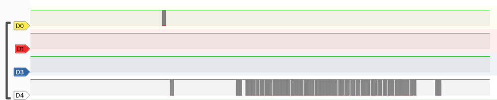
This was not what I expected. None of this looks like i2c data since there would be a clock and data pair. After looking at the HDMI pinouts some more I realized my mistake. There's 5 differential shielded pairs in my cable, one of them is used for the DDC data pair. But then what is happening on D4?
One of the other busses in the HDMI cable is CEC, the Consume Electronics Control signalling. This is used to send commands from your TV to a set-top box or DVD player. Instead of being a two wire bus this is a single wire bidirectional signalling system that follows the AV.link standard. Let's label that wire and see what Pulseview can decode from it.
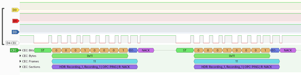
Here is the view with the CEC decoder added and zoomed in on the initial little blip of data on the CEC wire. So what's happening here?
The bottom row of the decoder shows the actual highest level decoding of the bits, in this case it's 2x the same message. CEC uses 4 bits for addressing and the first byte of a packet contains the sender and receiver address. The blue "EO..." bit in this screenshot is the End Of Message byte which is true in this message indicating there's no more data for this frame. A frame with only the addresses is a PING command as indicated by the decoder. This is a message send by the device on power-up to check if a device at address 1 (Recording_1) already exist on the bus. If such a device exists it will pull the CEC line down directly after the EOM bit. In this case that didn't happen which results in the NACK bit at the end of the message.
So what's happening here is that either the camera or the switcher is checking the CEC bus to see if the address it wants to use already exists and not getting a ping response 2 times.
So the next message:
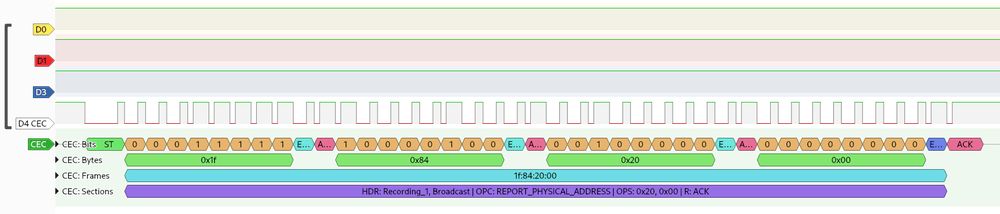
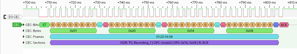
So here device 1 is sending a broadcast (destination 0xF) and it contains 3 more bytes of data. This means the second byte (0x84) is the opcode. In this case it's REPORT_PHYSICAL_ADDRESS and the last 2 bytes are the arguments for the command. There seems to be 2 addressing systems in CEC, the 4 bit address that's used for routing packets and a physical address, and this is the device at CEC address 1 broadcasting that it's physical address is 0x20 which decodes to address 2.0.0.0. The camera is connected to port 2 of the atem, if I move it to port 4 it becomes 4.0.0.0.
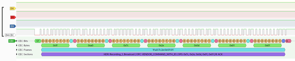
The the next command is a vendor command, so here the guessing starts again. the 0xA0 opcode that means the next 3 bytes are the vendor ID and the rest is the vendor specific command.
The 0x7c2e0d that's received after that is the mac OID for Blackmagic Design, so we're getting somewhere at least with this. Then the next bytes are 0x01 and 0x01. Now the hard part is figuring out what that means.
BMD vendor commands
So I found that by connecting a raspberry pi to the atem switcher I can monitor the CEC traffic it gets. Sadly it doesn't get a copy of all the CEC traffic happening in thee switcher as the standard says it should do. It does get CEC broadcast data instead.
From a quick look at some atem features that causes broadcasts to all devices, the first byte of the vendor data is a command ID and the rest is the argument. Command 0x03 is used to start/stop recording on all attached hardware where the first argument is 0x01 to start and 0x00 to stop.
Command 0x02 is the tally status command with the bytes following it being a bitfield for the tally. From a 4 port atem mini:
The program/preview controlled by the hardware panel:
Program 1, Preview 1: 0x03 0x00
Program 2, Preview 2: 0x30 0x00
Program 3, Preview 3: 0x00 0x03
Program 4, Preview 4: 0x00 0x30

Seperate program and preview tally:
Program 1, Preview 3: 0x01 0x02
So the data for this command is 2 bits per input, 2 bits wasted. The whole thing is little endian.
So my protocol docs so far:
| cec vendor command | command | args | notes |
|---|---|---|---|
| 0x1f 0xa0 0x7c2e0d | 0x01 | 1 byte | unknown |
| 0x1f 0xa0 0x7c2e0d | 0x02 | 4 bits per channel | Tally status bit 0 is preview bit 1 is program bit 2 and 3 are reserved |
| 0x1f 0xa0 0x7c2e0d | 0x03 | 1 byte | Trigger record 0x00 = stop 0x01 = start |
Interestingly, from sniffing the HDMI cable it looks like the color shading commands for the camera don't use the cec vendor command but they use just random (as far as I can tel) CEC opcodes. I have not been able to find just a list of CEC opcodes and their arguments so I can't really verify this. The CEC decoder in PulseView also doesn't seem to support all opcodes.
Camera control commands
| addr | opcode | args | notes |
|---|---|---|---|
| 0x01 | 0x19 | ? | Lift W |
| 0x01 | 0x19 | ? | Lift W |
| 0x01 | 0x1e | ? | Saturation |
| 0x01 | 0x1d | ? | Hue |
| 0x01 | 0x20 | ? | Contrast |
| 0x01 | 0x42 | u16 | Aperture |
| 0x01 | 0x46 | i16 | Zoom |
| 0x01 | 0x52 | i8 | Gain, signed byte 0xf4 = -12dB |
| 0x01 | 0x54 | u8 | White balance 0x32 = 2500k, 50k per step |
| 0x01 | 0x55 | u8 | White balance tint Unknown format |
| 0x01 | 0x57 | i8 | Shutter |
So this is a list of a few of the full CEC packets sent when shading a camera, some of the signed values are a bit weird, becoming 2 bytes when they are negative and 1 byte when they are positive. Here's the contrast message for example:
Most of these controls don't have a neat numeric value to compare against in the ATEM Software Control software so to get the exact encoding it would be required to implement that in OpenSwitcher first.
Also to figure out the commands that are not implemented yet in ATEMSC I need to find a way to inject CEC commands between the camera and the atem. There's some USB solutions that might work, it's also possible with an arduino and a HDMI breakout. In either case I need to wait for parts so that will be a part 2 of this series.
With the protocol decoded it would be possible to do a few neat things, like make a cheap (and I mean really really cheap) injector to put between the network and the HDMI cable of the camera to remotely shade one of these cameras when you're not on the ATEM mini hardware but on the older generation of hardware instead.