
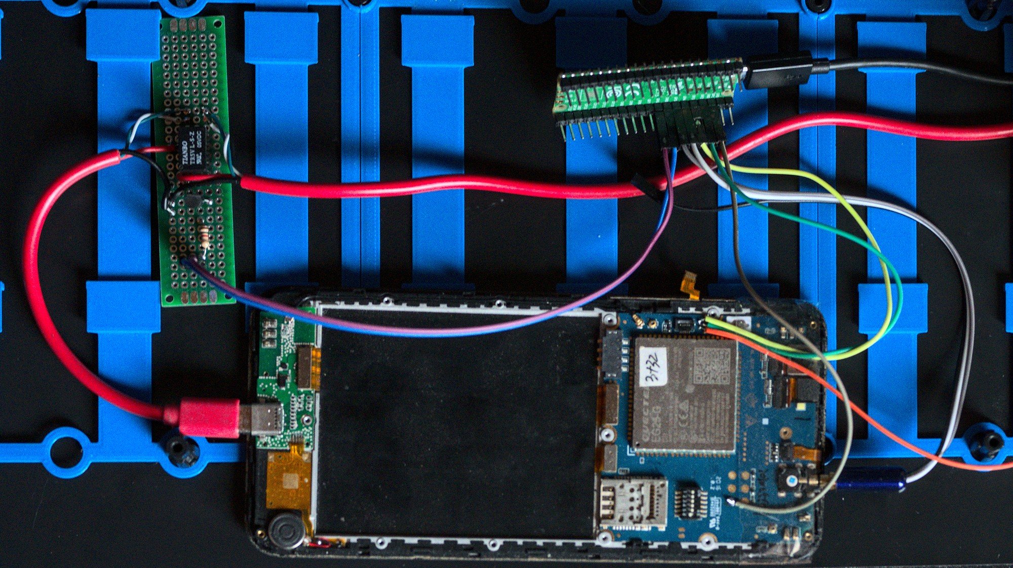
In part 1 I hooked up a PinePhone to a Raspberry Pi Pico and wrote the first iteration of the firmware for that setup. For testing I had used one USB port for the Pi Pico, one port for the PINE64 Serial cable and one for the PinePhone itself.
By using 3 USB ports per device I would run out of USB ports on the control computer pretty fast. This is why I picked the Pi Pico, it's not only cheap and available but also is able to emulate multiple USB serial ports at the same time. This required a rework of how the USB protocol was implemented.
The "default" way to use the USB serial port on the Pico is to call printf() to write data to stdout in the firmware and configure the build scripts to enable USB uart. This will make the Pico create an USB CDC ACM serial port on the usb port and it will be hooked into stdout/stdin. To add a second ACM interface none of this automated setup can be used at all.
The second revision of the firmware replaces the printf/getchar usage with directly using the tinyUSB library. Using this I can manually define all USB descriptors I need and hook them up into the parts of the firmware where I need them. With my own descriptors it means the device no longer shows up as Raspberry Pi Pico in lsusb, instead it's now "postmarketOS Test Device".
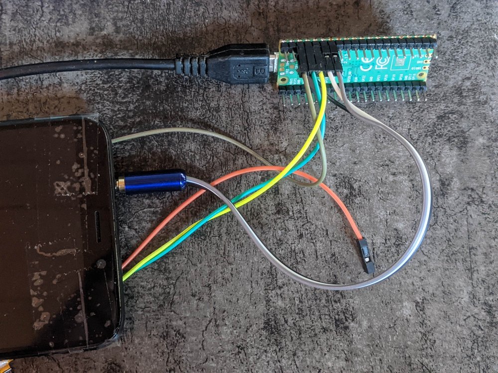
Ignoring all the extra setup code to get tinyUSB running, the changes to the existing parts of the firmware is mostly replacing getchar with tud_cdc_n_read which accepts the port number to read from, and replacing printf with tud_cdc_n_write_str. One additional piece of the firmware now reads bytes from the USB CDC 2 port and writes it to the hardware uart1 on the Pi Pico and vice versa. With this and a tiny extra cable I fully replaced the need of the USB to serial adapter, freeing up one USB port per test device.
Power switching
One other feature that was not implemented yet in the previous blog post is power switching. To bring the device in a known state it's easiest to just turn it off and on again. Since having someone sitting beside the test rack to pull out the USB cable is not very practical I needed a way to interrupt the power lines in the USB cable going to the phone. This is slightly more complicated than wiring some test pads directly to the pins of the Pico so to not hold up the software development parts of this I made a test PCB that allows me to control the power of an USB cable:
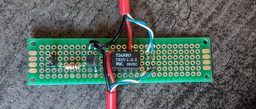
This is a piece of protoboard put in the middle of one of the red pine64 USB cables. It has a relay that interrupts the 5V line inside this usb cable and the data lines are passed through directly. It also includes the circuitry to control this relay from the Pi Pico when hooked up to the 2 pins to the left of the board. For those that know electronics; the diode that is missing in this picture is on the bottom of the board.
For the final version in the test setup this won't be a seperate board, it will also not use a relay. Relays have a limited number of operations and they make noise. Having mechanical parts in a test setup is not good for reliability in any case. This will be replaced by a solid state method of switching power, most likely a mosfet.
This board is then hooked up to the ground and GPIO 6 of the Pi Pico and it will make the p/P command work for switching the phone power.
The central controller
To have a look all the way to the other end of the development for this project, the webapplication that will control it all. This is the interface presented towards the developers that will use the test setup.
This piece of software is comparable to something like Lava from Linaro. It has a webinterface to submit and view the builds and have an overview of the devices. The things I'm doing differently compared to Lava is not using jinja2 templates for configuration and having a passthrough mode for scheduling a live connection to a device in the test rack.
The implementation of the central controller is partially modelled after the way Sourcehut Builds works. It will mostly act like a regular CI system but it's backed by physical hardware instead of VMs or containers. It also aims to integrate some of the features that makes sr.ht builds nice to work with like being able to get a shell into the test environment so you don't have to keep submitting slightly changed CI jobs multiple times to debug things. Also having nice split logs for the CI tasks.
The first thing to look at is how devices are defined in the test system. The information is intentionally kept minimal. There's a definition of a device type which is just a name, chipset and architecture. In the case of postmarketOS this name would be the postmarketOS device code like pine64-pinephone
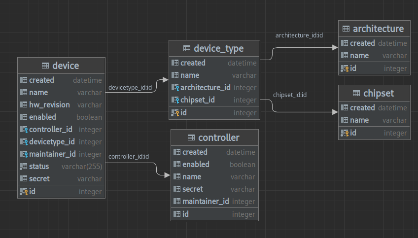
For every device in the test rack a row in the device table would be created. This row can have an addition hardware revision number, like 1.2B for a PinePhone, and contains information about which controller it is connected to and which user the maintainer for this device is.
This by itself is not enough to do all the required test scheduling things. There needs to be a way to specify extra information that can be queried in the test jobs or can be used for filtering devices. For this there's another part in the schema:
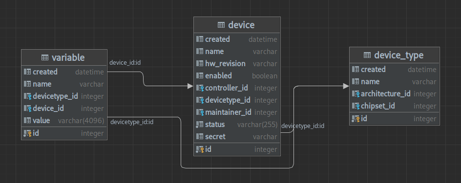
There is a variable table that is an arbitrary key-value store for extra data. This data can be used for selecting on which devices to run specific tasks and the values will also be available in things like environment variables. The variable table defines data at three different levels. if device_id and devicetype_id is unset in a row it will be a global variable for the whole test system. Then variables can be defined at the device type level and then again at the device level. The job specification itself also contains a fourth level of variables that will be defined in the job description format.
When a job is run all the variables for the current device will be looked up and combined in a cascading system. Device type variables override global variables with the same name, same with device variables and job variables. This data will be then appended to the job that is submitted to the controller and executed.
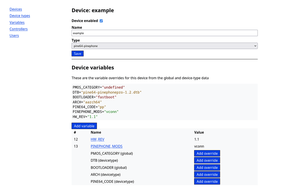
Some examples for variables in my current test setup are PMOS_CATEGORY which sets in which postmarketOS device classification category the device is., to make it possible to run a testjob on all the devices in the main or community category. Another is the DTB variable that sets what the device tree name is for the specific devices. This is something that would be a device-type variable for a lot of devices, but would be overriden on the device level for the PinePhone due to hardware revisions that have seperate upstream device tree files
The user facing parts
The webapplication has three levels of authentications. Guests, Developers and Admins. Visitors that are not signed in get the guest role and can see the status dashboard and all the job results, similar how build.postmarketos.org lets guests see the state of the postmarketOS build system.
Accounts are created for developers, which grants the permission to submit new jobs in the system. For all the other administration tasks there's the admin role which allows linking controllers, defining devices and creating new accounts.
The device editing part of the administration interface is already shown in the screenshot above. The admin panel gives access to all the settings in the application so it's not necessary to have a shell on the server running it to do administration tasks.
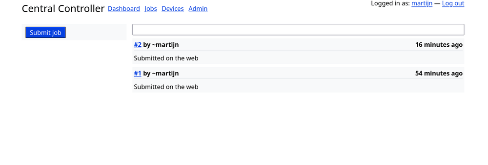
Guests visiting the webapplication will land on the dashboard:
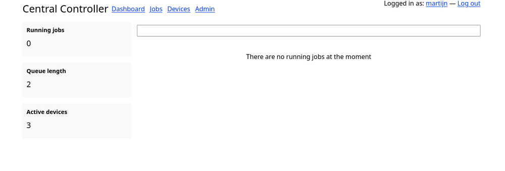
This shows all the currently running jobs of which there are none since the controller is not implemented yet. It also gives some quick statistics on the side about the overall system.
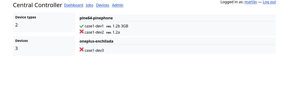
The more detailed information is shown on the Jobs and Devices page. The devices page shows a list of the defined device types and the active registered devices. In my case the device naming tells me which rack case the device is in and the slot number.
And finally the jobs page. It shows a list of all queued, running and completed jobs. The internal terminology for the overall system is: jobs are the manifests submitted by the user, tasks are generated from the job for every single matching device. If the job specifies exactly one device with the filters it will generate a single task which might have subtasks for test output legibility.
Future improvements to this is showing the status of all the tasks in the job in this job listing. For logged in developers there's the option to submit a new job in the sidebar. This links to the job creation page. This is all very similar to the workflow in builds.sr.ht which this is based on.
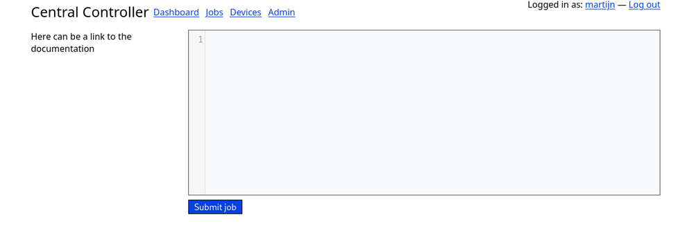
Jobs are submitted using a code editor page. All the information of this job is part of the job manifest so it's easy to copy and paste parts of job configurations. Documentation has to be written once the job description format is stable.
Finally there's the job detail page. This shows the job result in real time.
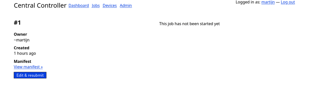
The contents of the job page will mainly be filled by text blocks streamed from the controller. Just like sr.ht there's an option to download the manifest for a job and jump to the job submission form with the current manifest loaded.
Controllers
The main system that will hook all the parts of the system together is the controller software. This will run on a machine in the test rack and will communicate with the central controller to fetch jobs. The controller will be implemented as a daemon and will be controlled using a command line utility. The API interface between the central controller and the rack controller has not been fully defined yet. Most of the tasks will be a regular REST HTTP api but the test results will need a more complicated data streaming setup.
Part of this communication is the possiblity to get a shell on a device that will emulate a regular SSH session. Since in the design the rack controller is not portforwarded this would need to be a reverse shell and it needs to be proxied on the central controller to allow developers to get to that shell from their own machine. This is a bit of a complication but it would make quite a few things a lot simpler like running kernel bisections remotely or even doing remote development in general.
Up to part 3
The next part of this system is figuring out what things are required in the job description format. Submitting a single script to a single phone is easy, dealing with differences between devices is the hard part. Also as a sneak peak into the future parts; the header image shows the 3d printed slots in the rack case the phones will slide into.