
Testing things is one of the most important aspects of a Linux distribution, especially one for phones where people rely on it being in a state where calls are possible.
For postmarketOS the testing is done manually for a large part. There's CI jobs running that verify that packages build correctly but that's as far as the automated part goes. For releases like service packs there is quiet a manual test process that involves upgrading the installation and checking if the device still boots and that the upgraded applications actually work.
With the growth of postmarketOS the things that need to be tested have grown massively. If there is a change that affects multiple devices then that process will take the majority of the time to get an image running with the changes on all the target devices, and in many cases it involves getting other device maintainers to try on their devices for big releases.
Automation
Automated testing for the devices postmarketOS supports is not very easy. Phones don't have the interfaces to fully automate a test process. To get a new image flashed on a phone it usually takes a few steps of holding the right key combinations and plugging in the usb cable at the right moment. This process is also significantly different for a lot of devices to complicate things further.
The goals for the automated testing are quite ambitious. The plan is to get as many devices as possible in a server rack hooked up to a computer with wires soldered to the phone to trigger the key combinations to control the boot process.
For the software side this would require some interface to let multiple developers schedule test jobs on the devices they need and an interface to keep track of the state of all the connected hardware. This is quite a lot like the scheduling and interface for a regular CI system and large parts of this system will be modelled after how Gitlab CI works.
This whole system will consist of many components:
- A central webapplication that keeps track of all the available hardware and schedules jobs. The webapplication does not contain any implementation details about hardware except for the names.
- A server application that connects to the central webapplication and registers connected devices. This application has the responsibilty of tracking the state of devices and asks for new jobs from the central server when a device is free. There can be many instances of this server application so there can be multiple test racks maintained by different developers.
- An application that is spawned for every job that actually executes the testcase and parses the output from the serial port of the device.
- A piece of hardware that can press the buttons on the phone and deal with plugging in the power at the right moments. This hardware should be mostly a generic PCB that can deal with the most common interfaces for devices. For devices with special requirements a new board can be made that controls that.
- A case design to hold many phones in a relatively dense configuration. It is estimated that there can fit around 8 phones in a 2U rack space with a generic enclosure and some 3D printed holders.
Splitting the software up this way should make this test setup scalable. The most complicated parts seem to be the central webapplication that should present a nice webinterface and deals with making it easy to run a test job on multiple devices, and the runner application that actually needs to deal with the hardware specific implementation details.
Since this is quite a setup to build I've decided to start as small as possible. First get a test running by making some prototype hardware and a prototype runner application that only supports the PinePhone.
The initial test hardware
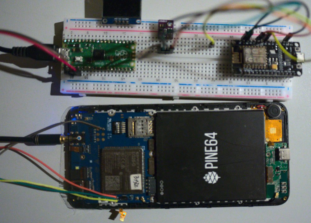
For the initial test hardware I'm using an off-the-shelf Raspberry Pi pico on a breadboard. Initial design revisions were based around an Atmel atmega32u4 to implement an usb-to-serial adapter and a second serial port for hardware control. Due to the chip shortage the popular Atmel parts are practically impossible to get.
The Pi Pico has a microcontroller that is able to emulate multiple USB serial adapters just like the Atmega32u4 and after dealing with getting the SDK running is actually quite easy to write firmware for.
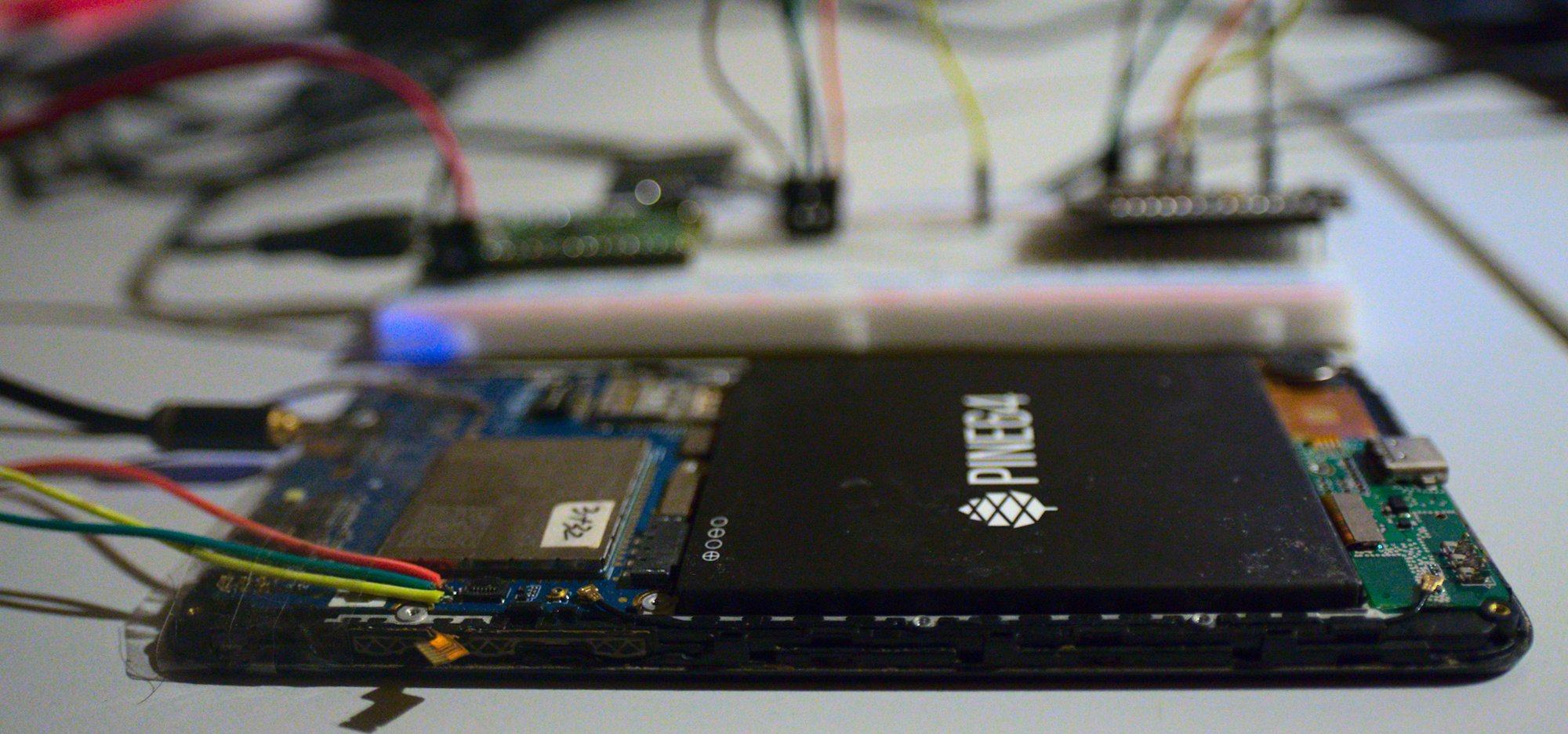
For this initial revision I'm only running a single USB serial device on the Pi Pico since the PinePhone has an easily accessible serial port with a PINE64 debug adapter. For controlling the buttons I have soldered a few wires to various test points on the PinePhone PCB.
The buttons on the PinePhone normally work by shorting a signal to ground. This is easily emulated with a microcontroller by having the gpio the test point is connected to configured as an input so the pin on the Pico becomes a high resistence that doesn't influence the PinePhone. When pressing the button the gpio can be set to output 0 so the signal is connected to ground.
After some testing with the Pico this works great, it took a while to figure out that the Raspberry Pi Pico enables internal pull-down resistors by default on the gpios, even when it's set to input. This caused the phone to think all the buttons were held down all the time.
Control protocol
To actually control the buttons from a computer a protocol is needed for sending those commands to the Pi Pico. After coming up with a custom protocol first I got pointed to cdba. This is a tool for booting images on boards which is exactly what I need.
This tool is designed to work with some specific control boards which I don't have, but the protocol used for those boards is incredibly simple.
Every command is a single character written to the serial port. For enabling power to the board a P is sent. For disabling the power a p is sent instead. This uppercase/lowercase system is also followed for holding down the power button B/b and the button required to get into a flasher mode R/r.
This is the protocol I implemented in my first iteration of this firmware. The nice thing is that the hardware should also work with cdba, if it is a fastboot device at least.
The code at this point is in this paste.
Test application
To verify this design I wrote a small test application in python. It connects to two serial ports and takes a PinePhone disk image to boot into.
The code used for the first sucessful flash is in this paste.
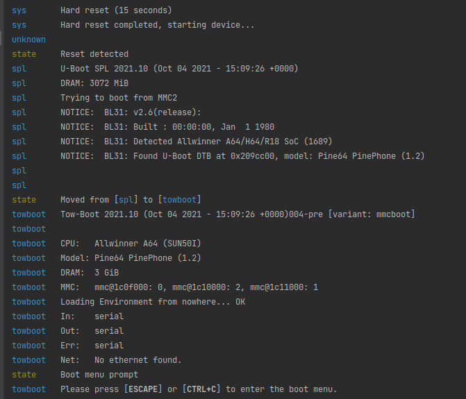
This application does multiple things. It first connects to the serial port of the Raspberry Pi Pico and resets all the state. Then it will hold the power button of the PinePhone for 15 seconds to force the phone in a known state.
It also connects to the PINE64 uart debug adapter and reads the serial debug logs of Tow-Boot and the kernel. By looking for specific lines in the serial output it knows where in the boot process the phone is and it uses that to hold the volume button to get Tow-Boot into the USB Mass Storage mode.
It then simply dd-s the disk image on the eMMC of the phone and restarts the device. Now the phone will boot into this new installation because this time the volume button is not held down while booting.
The things that needs to be implemented after this detecting when the device is booted and logging in on the serial console so it can run the test script.
This iteration of the script also hardcodes a lot of sleep times and device paths. Hardcoding the path to the block device works somewhat reliably on my laptop but it will fail in production when multiple devices are connected and booting in a random order. This can be fixed by specifing which USB ports the phone and test board are plugged into instead and using udev to figure out what block device and serial device belongs to which phone.
Next steps
The most important next thing to figure out in the application is designing a job description system so developers can write testcases to run. Also using this setup finding quirks in the boot process can be ironed out, like the application only flashing the phone correctly half the time because it sometimes boots the OS instead of getting into the bootloader.
I have also already written some major parts of the central webapplication that actually deals with registering devices and data about those that can be used as variables in the test jobs.
Once those parts integrate it would be important to get a second device up and running in the test rig like the Oneplus 6 to avoid overfitting the design to the PinePhone.