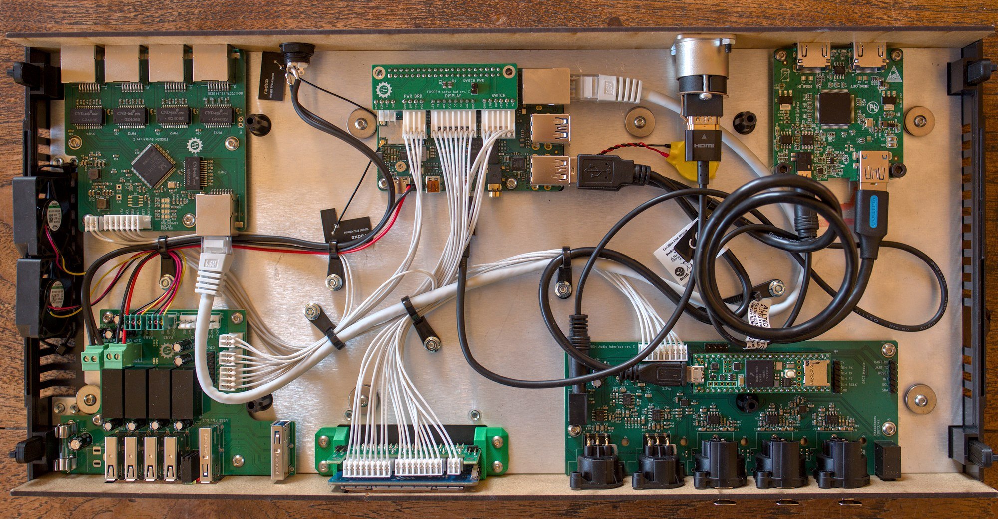
The FOSDEM video capture box is a custom device for doing all the in-room stuff for the live-streams of the event. It contains a Radxa x4 SBC, a digital audio mixer, an HDMI capture card, some USB chargers and a network switch. Every room that is livestreamed has two of these boxes, one in front that captures the audio and the HDMI signal for the projector. The other box is in the back of the room hooked up to the camera.

The network switch is the managed network switch I've written about before, but instead of being hooked up to an ARM computer and using the DSA system in Linux to make it appear native it's mostly unmanaged here. There is connectivity between the switch and the radxa only for some basic monitoring.
The audio mixer here is also the digital audio mixer design I've written about before. It's handling the audio input from the wireless microphones used at FOSDEM and it sends out the audio to the XLR inputs on the camera used for recording.
The power board is another custom designed board by Dexter, it takes 12V from the wall and provides the power for all the internal components, it also provides 4 USB charging ports in the front which are electrically isolated from the rest of the system to have the wireless receivers plugged into the chargers without creating ground loops. This boards also has a few auxilary functions like controlling the fans in the box.
A talk has also been given about this hardware at FOSDEM itself (at the end of the event after we were sure everything was working smoothly) and is watchable at https://fosdem.org/2025/schedule/event/fosdem-2025-6832-fosdem-videobox-2025/.

To add a bit of irony to the situation this talk about fixing audio quality issues at FOSDEM has bad audio because we decided at the last moment to plug in a spare wireless mic into the system to have mic handoffs and had the gain of the receiver set higher than the box volume could be adjusted.
Next up after FOSDEM
The hardware worked great during the event and now the pressure of having it work at all is gone some extra time has been spend on fixing up issues in the design.
One of the more annoying things about the box is that you can hear it in the recordings and in the rooms because the fans are too loud. This is a combination of various design tradeoffs. The first is that the fans are hooked up to an EMC2305 fan controller chip. This chip is also used in a few computers as the internal fan controller. Sadly the automatic control functionality of this chip simply doesn't work (and we checked the Linux kernel driver for it, it also doesn't use the automatic functions). In this design it's only used to read the tachometer signals of the fans and output the PWM signal for the fans.
The second issue is that the fans don't have a PWM input so the fan control is done by applying the PWM signal to the power input. Due to this control mechanic and the limitation that the PWM of the fan controller chip has only 8 bit resolution the usable range of control for the fan is reduced to ~6 levels where there's measureable difference in the fan speed, and the only real levels there are off, slow and 4 levels of way too loud.
The firmware that ran at FOSDEM had a control loop on the fans that measured the fan RPM and adjusted the PWM signal to keep the fan speed at a preset PWM which due to the limited control resolution just meant the system occasionally started oscillating and the fan speed was ramped up a lot due to the anti-stall mechanism.
This has now been replaced by a far simpler control loop that only allows setting "off, low and fast" so it matches reality and not use any tachometer feedback to control this but instead only use that for stall detection.
Audio firmware changes

The audio mixer at fosdem did not use the USB audio path at all, the audio signals were mixed and then the analog XLR outputs were used to send the audio to the speakers in the room if available, and to the audio input of the camera so the audio is embedded into the HDMI signal that is captured. This is mainly to maintain sync between audio and video through the system. The firmware running at FOSDEM had stability issues when using the USB soundcard functionality of the box which luckily wasn't needed.
But these boxes are not only used at FOSDEM, it would be a shame to make custom hardware that is only used 2 days per year. The boxes are loaned out to other conferences to try it out and one of those conferences is FOSSASIA in Bankok. On this conference there is no HDMI camera used for the capture in the rear of the room but instead it's using a webcam, and webcams don't have inputs for audio input. After figuring out that it was the patches to run the Teensy audio board at 48KHz sampling rate instead of 44.1KHz it was decided that those patches should just be ripped out. So far the firmware has been stable with these changes.
VLAN support for the network switch

The network switch in the box has performed perfectly during the FOSDEM event but none of the fancy features of the switch chip were used. The main thing that was done was reading out the port status so it can be shown on the display on the front of the box.
For more flexibility it would be nice to give this more managed switch functions, one of the main things being VLAN support. The basic functionality for the switch is very easy since you just supply the chip with power and it starts switching, figuring out how to control the chip itself is way harder. There's not nearly enough public information available on programming the RTL8367S, the datasheet only covers the registers for port status that I've been using.
Using a lot of puzzling and reverse engineering I've figured out how to load a VLAN config into the chip. This is mainly based around bits of info available from other realtek switch chips and some bits of leaked SDK code for similar chips. This means there's now some extra APIs available in the rp2040 code that controls the switch in the box for setting up a static vlan configuration on boot:
// Set the MemberConfig for all ports to 0 and enable tag handling on the ports
nsw_vlan_init();

// Enable the VLAN processing in the switch
nsw_config_vlans(true);

// Create a VLAN table entry for VLAN 10 with port 1, 2 and 3 as members
// Port 2 and 3 will be untagged on egress
nsw_vlan_cfg_t vlan10 = {
		.vid = 10,
		.mbr = BIT(0) | BIT(1) | BIT(2),
		.untag = BIT(1) | BIT(2),
};
nsw_vlan_set(&vlan10);

// Create a MemberConfig row to ingress untagged traffic on port 2 and 3
// Use MemberConfig index 1 and vlan 10
nsw_mc_set(1, 10, BIT(1) | BIT(2));

// Point the two untagged ports to MemberConfig index 1. This needs to
// happen _after_ setting the ports as member in the MemberConfig itself
nsw_port_set_mc(1, 1);
nsw_port_set_mc(1, 2);

// Set the untagged ports to drop traffic with a vlan tag set
nsw_port_vlan_filtering(1, PORT_ACCEPT_UNTAGGED_ONLY);
nsw_port_vlan_filtering(2, PORT_ACCEPT_UNTAGGED_ONLY);

// Drop untagged traffic from the trunk port
nsw_port_vlan_filtering(2, PORT_ACCEPT_TAGGED_ONLY);
There's also half an implementation for reading port statistics. The switch provides the standard port statistics MIB block, I just need to figure out the final bits for mapping the MIB numbers to the right address in memory.
The current port status information that's read out of the PHY registers of the switch are equivalent of the data in the ethtool eth0 command, the MIB registers contain the information presented in the ethtool -S eth0 command. This would great to produce some pretty Grafana charts.
Hardware improvements
The audio board performed decently given the constraints of the FOSDEM environment and the hardware plugged into it, but I'd like it to be a bit more flexible. The XLR inputs right now are designed to accept -10dBu consumer line level signals. Plugging in a cheap microphone doesn't really work since the board does not have enough gain available to crank up the levels in hardware and is also too noisy to just boost the levels in software. It is also possible to clip the inputs using the AVX wireless systems used at FOSDEM which also isn't ideal.
The reason for the small dynamic range of the inputs is for the FOSDEM constraints the simplest and most reliable solution was to make an analog frontend that works from the 5V usb power directly and is tweaked line level signals. The initial version of the board had switching regulators on it to produce +12V and -12V power rails for the analog inputs and the filtering for these inputs was not enough. To make some more HiFi inputs I'm now working on some prototypes of better power supplies and have some new designs around better ADCs and better analog frontends.

This design of the power supply reverts back to the original switching regulator but now uses the filtering circuitry used with the 5V powered analog inputs of the FOSDEM hardware to hopefully produce a less noisy signal. The redesign for audio input also replaces the integrated TI codec which has a lot of issues with a dedicated ADC and DAC chip, one of the major improvements here is that the inputs of these ADC chips is already balanced so the board doesn't have any unbalanced audio signals on it anymore.
One of the main things that needs figuring out is how to have cheap software control of the input gain, for using cheap wired microphones it would be needed to boost the signal levels a lot, somewhere between 40 and 60 dB of extra gain without too much noise added. There are easy solutions for this, but the easy solutions are never cheap, especially considering you need a copy of the circuit for every input channel.
Having some better input circuitry would make the FOSS digital audio mixer a lot more widely usable, there's many situations where I really would've used a small audio mixer to do some simple routing.
See also
Want to read more about the FOSDEM hardware? Other video team members have also written some blog posts about other details: