
Since writing my previous post about the digital audio mixing I've made some significant progress. Initially my code was running on an off-the-shelf Teensy 4.1 and using only the digital input and output I could use directly with an external ADC/DAC. Shortly after writing that post I received the Teensy Audio Shield which makes the test setup a bit easier to deal with.

This is a simple board that connects an NXP SGTL5000 codec chip to the Teensy. It provides a stereo in and output on the header at the top in this picture. It also has a fairly decent built-in headphone amplifier which is exposed with the 3.5mm jack at the bottom of the picture.

With this board I replaced the S/PDIF input and output in the code with an i2s interface which completed this into a self-contained 2-input and 2-output audio mixer. But how to expand from here? That's more in the realm of custom hardware since the Teensy Audio Shield is practically the only board you can order for Teensy Audio.
So a custom board... There's a few other supported codecs by the audio library. The issue is that most of the codecs in the list are EOL or not recommended for new designs. They are also mostly out of stock so I postponed this idea for a bit.
FOSDEM 2024
So roughly at this point in the process FOSDEM happened. Not only is this a very interesting open source software event but it also manages to run ~30 concurrent live streams and in-room audio mixes with an ad-hoc setup with only about a tenth of the amount of personnel you'd expect to be needed to pull this off.
To pull this off FOSDEM uses custom build "video boxes" that contain half the equipment needed to run all the multimedia in every room. Two of these (identical) boxes are put in each room for the complete setup. This setup has evolved a lot over the years.
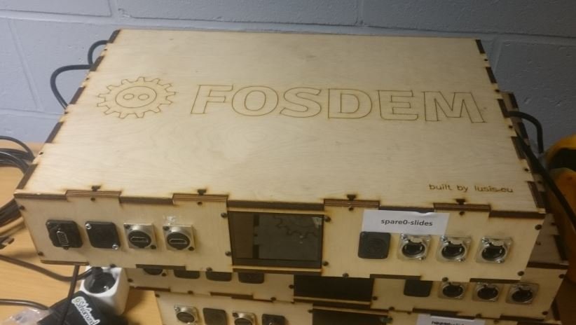
This is one of the examples: the nice laser-cut video boxes used from ~2015 to 2023. These have the job of capturing from the HDMI video inputs and send off the video from the connected camera and speaker laptop to be encoded for the live-stream. This is a very nice and compact solution for deploying a room for FOSDEM and during the event these are controlled remotely from the central operations center allowing only a few people to monitor and manage all the video streams.
But what about the audio? There's a microphone for the speaker and one or two microphones for audience questions but these don't hook up to the custom boxes. The room audio in most rooms is handled by a Yamaha MG10 audio desk. This is easily enough for mixing together the audio from 4 sources but has one major downside: you have to be physically present to turn the knobs to adjust anything.
While video is usually pretty great while watching back the talks I've noticed there's sometimes a few audio issues like microphones that are clipping. The perfect solution for this all is a digital audio mixer that can be controlled remotely of course, but those are way larger and more expensive.
It turns out FOSDEM is that perfect target for a 4-in 4-out audio mixer that is controlled over USB instead of physical controls. I'm very glad I managed to meet up with the FOSDEM video team, which lead to...
FOSDEM Audio Board
So the FOSDEM setup has a few very interesting constraints for an audio mixer:
- There's two audio mixes, one for in-room audio and one for the live-stream
- All mixes are mono, there's not much sense in stereo for running a few microphones.
- All sources are line-level. The microphones at FOSDEM are all wireless and the receivers can output line-level signals so no need for microphone pre-amps. This massively simplifies the design of the analog inputs.
- Since no condenser microphones or phantom-powered DI boxes are used no +48V phantom power supply is required.
- The current iteration of video boxes are inside 19" 1U rack cases which constrains the size of the audio mixer a lot.
So I have practically no experience with designing audio gear. Luckily the additional constraints massively simplify the design which is great for cost optimization as well. So I did the most dangerous thing a software developer can do: I launched Kicad.

For the design I decided to put two of the SGTL5000 codecs on the board. It's one of the few supported codecs that are still available and they already deal nicely with line-level signals. Another great feature of these chips is that they include analog gain control which saves me from having to implement a digital-controlled analog gain circuit which sounds difficult and expensive. Having a built-in headphone amp is also great for adding a headphone connection for monitoring in the room.

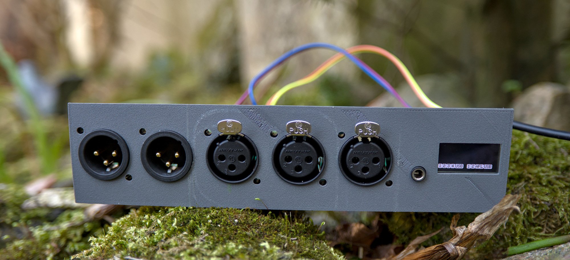
This is how the hardware is connected internally. There are 3 analog XLR inputs for connecting the microphone receivers and the fourth input is a 3.5mm jack that is hooked up for some simple analog mono-summing of the incoming signal. This 3.5mm jack will connect to the audio output of the HDMI capture card connected to the laptop of the presenter.
One of the codecs also provides the 2 XLR outputs. One connects to the existing audio speakers in the room and the other connects to the audio input of the camera. The headphone connector is connected to the outputs of the second codec so that audio mix can be controlled separately in software.
The only thing that needs to happen in addition to the schematic of the original Teensy Audio Shield is dealing with balanced signals. Sadly there isn't a "getting started with designing audio interfaces" book but I found the brilliant website from Elliot Sound Products that has a lot of information on these circuits. The inputs and outputs have a pair of opamps to convert the signals. This is implemented with TL072 opamps because they are cheap, available and have 2 opamps in a single chip. This means the whole input circuit is a single chip and a few passives.

The other part that needed figuring out is the power part. This surprisingly was a lot more work than the actual analog audio handling. The whole design is powered from 5V from the USB port but there is a lot of separate voltages needed to run all the audio hardware.
The codec chips need two 3.3v rails and one 1.8v rail to function. One of the 3.3v rails is for the digital part and one for the analog part. The opamp circuits are even more complicated because they need a positive and negative voltage rail to function.
The exact voltage for the opamps does not matter much but it has to be high enough that they are always above the analog audio input levels and because these are cheap opamps it needs a few volts extra because the TL072 cannot process signals close to the supply voltage which results in distortion. On the other hand the output voltage needs to be below 40 volts because I'm building an audio interface and not a smoke machine. In this design the supplies are +9V and -9V which brings the total voltage on the opamp to 18V.
To generate the positive and negative 9V rails I first generate +12V and -12V with a switching regulator and then feed those into an LDO to filter out the switching noise from the switching regulator. After dealing with all this I now finally understand why so much of the audio gear has old-school transformers to power them: it makes it very easy to make a dual-rail supply.
It was not easy to figure out how to get the dual rails from 5V at all. To start I decided to open up one of the USB powered audio interfaces I already had and see what the designers of that device did to fix this. In this case it was a Tascam US-2x2.
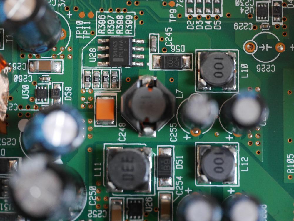
This is a picture of the power supply section of that audio interface. It contains a lot of different voltage regulators to make the various rails. It has to deal with a few extra voltages compared to my design since this also has +48V phantom power. After measuring it the main negative rail of this board was generated by the 34063 chip at the top of that picture. This is used as an inverting switching regulator in this case. The positive rail for opamps in this design is generated by the tiny chip labelled U26 all the way on the bottom of the picture, I've not been able to identify this chip.
This all together lead to my initial design:

The top left part of the board generates the voltages for the opamp circuits and the top right has the regulators for the codecs (and the PC input jack). This version of the power supply was not complete yet since it was lacking a few capacitors and I found out that the inductor I selected was way too small to function correctly.
This revision of the power supply was scrapped because with the correct inductor the power supply simply became too large for the board and I didn't want to make the board any larger since the inside of the FOSDEM box is very space constrained.
The MCP34063 is also decades old technology by now. It's a switching regulator that runs at 100Khz max. In this design the switching frequency would be ~60Khz but this results in needing a large capacitor and inductor on the board.
In the current revision of the board this has been replaced with the TPS65130 regulator. This is a way more modern switching regulator running at 1.3Mhz instead. This chip is a bit more expensive but it generates both the positive rail and negative rail with a single chip and due to the order of magnitude larger switching frequency the inductor and capacitor can be way smaller. The end result is a more compact and cheaper power supply.

This is the board that was ordered as prototype. It's mostly the same as the board shown above but it has an extra header exposing a few I/O pins of the teensy for prototyping and the PC input connector has moved so the jack will be above the board to waste less space in the case.
The actual hardware
After waiting some days I received this partially assembled board:

After soldering on the connectors I powered it on and checked the voltage rails, it all seemed fine. Then after powering it on a second time it started making a screeching coil-whine sound and within a second the 12V generator made the bottom of the PCB too hot to touch. After initially working for a bit I didn't get it to generate the correct voltages again, even after restarting the board. Sometimes when powering it on it heated up again, sometimes it didn't but for some reason the output of the +/- 12V supply was +6V/-4.5V instead.
This issue plagued me for some days until one day I had plugged in my headphones in the board while measuring things with the multimeter and suddenly the weird noise from the inputs disappeared. This happened when I had the probe of the multimeter on one of the pads of the diode for the negative supply.
It turns out that the solder connection on that diode was not reliable and after heating up that pad with a soldering iron for a second I managed to get the board running at the right voltage again... but only sometimes. At least the board was now reliable enough that I could work a bit on the firmware and all the functionality that didn't depend on the opamps was working great.
This is one of the moments where it's a massive help when other people double-check your schematics. It turns out I copy-pasted a few capacitors and forgot to adjust the values. Specifically I had a capacitor in the feedback path for the switching regulator that was two orders of magnitude too large. It turns out those capacitors were optional anyway according to the datasheet so after removing those from the power supply it already became a lot more reliable. Still it sometimes failed to start and unreliable equipment in a live environment is a non-starter.
After verifying everything it turned out that there were more capacitors with wrong values and sadly these capacitors were actually required. So I took the boards to someone with actual electronics experience and also the correct gear to debug the boards. A few capacitors have been removed, a few have been added and the result is beautiful soldering work like this:

Which is a 100nF capacitor soldered on top of an 10uF capacitor to further reduce the ripple of the power supply. The board has since been adjusted to actually have these capacitors included. After an evening of messing with the board to minimize ripple the switching regulator section has turned into quite a battlefield:

A few stacked capacitors, a pad I've accidentally ripped when removing capacitors. The power-save pins on the regulator connected to GND instead of VCC and in the bottom left corner a beautiful stack of 3 capacitors and a 1k resistor on the output of the regulator.
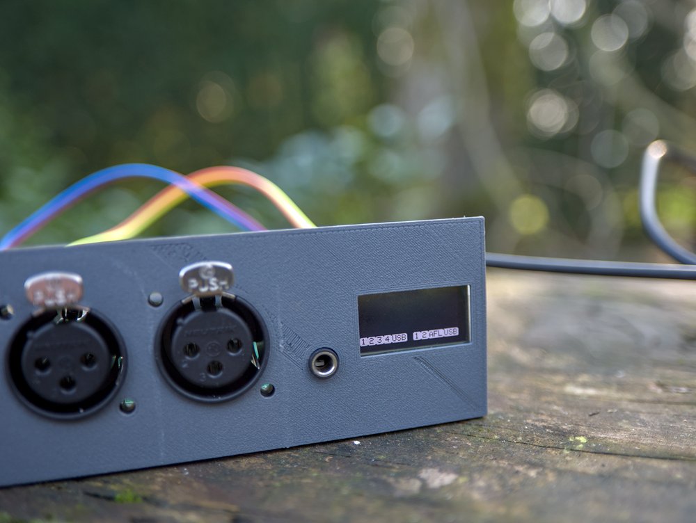
Luckily after all this the regulator started working reliably. To make it a bit nicer on my desk I also 3d printed a simple front panel for the mixer. I also got a random oled panel from my parts box and connected that to the GPIO pins so I can have a display to show real-time debugging information while testing the software.

The source Kicad files for the audio board are available at https://git.sr.ht/~martijnbraam/mixolydian-4x4
The software side
For the software I started off from the Arduino IDE project I had for my previous blog post. The design for the audio at FOSDEM would be simpler though, no networking is needed at the mixer but instead the USB connection would be used for control. Adding a network port for the audio mixer would mean it needs more switch ports in the box and since the network switch ports are on the outside it would need an ugly cable coming out to the front of the box to connect it up.
The control of the mixer would happen through the infrastructure FOSDEM already has where the volunteers in the rooms can control the boxes with a webpage from a phone and some software on the SBC inside the box will communicate with the mixer over a serial port.
There were also a few small software issues to deal with due to the hardware. There are two SGTL5000 codecs on the board. There are two variants of this chip, the 32 and the 20 pin version where the major difference with the 20 pin version is that it doesn't have any address pins for the I²C bus. Sadly the 32 pin variant wasn't really available so the codecs are now using the same address but on different I²C busses of the Teensy. The audio library is hard-coded to have the codec on I²C0 of the Teensy so this requires a bit of patching.
The issue of patching the Teensy audio library is that libraries in the Arduino build system are a mess and the audio library is also part of the Teensy core in the IDE instead of a separate library. After messing with it to try to make it a bit more sane I decided to convert the Arduino IDE project to a plain cmake project that pulls in the various parts of the Teensy core as git submodules and has the whole audio library vendored in. This also means it's now possible to build the firmware for the FOSDEM audio mixer without first downloading a pre-compiled ARM compiler so it can run quickly in Alpine in CI.
The code for the cmake-ified project is available at https://git.sr.ht/~martijnbraam/mixolydian-4x4-fw
I had also added an OLED panel to the board for testing so I added a bit of code that displays the audio levels of all the inputs and outputs of the board on that screen.
This part will definitely be different on the FOSDEM boxes since these oleds are very small and the PCB behind it are large enough that it barely fits in the height of an 1U rack case. It is very cool to have audio level bars in realtime though and if there is a color display it could even be usable enough to see if the levels are correct.
There's also an initial implementation of the serial control protocol. The exact protocol has not been fully thought out yet but at least it does the one thing all serial protocols should do: print something useful when sending a newline.

When sending a newline to the interface it will print the state of the mixing matrix as percentages.
The source code is of course available at
Further work
The audio interface has been tested with one of the wireless sets from FOSDEM, which is a Sennheiser AVX ME2 set. The audio seems to work great with this and for running FOSDEM there can simply be 3 receivers plugged into the box.

But can this be simpler? The AVX system works with DECT chips so maybe it would be possible to make the worlds first digital audio mixer with built-in DECT base-station :D
Conclusion
This is certainly a lot of progress for the audio hardware part of the mixer project. While a lot of the hardware is specified for the exact requirements of a FOSDEM room it does provide a neat base to work off for designing digital audio mixers. The parts of the hardware design are modular enough to reconfigure them for other audio needs and now the line-level inputs are working it will be neat to figure out a digitally controlled microphone preamp. Or have hi-z input for instruments. Or implement a phantom power supply.
It's always a ton of fun to figure out new systems and instead of learning a random new programming language it's hardware design stuff for once. I absolutely couldn't've done it without the expertise of the electrical engineers that helped me design this, especially Thea who actually knows how switching regulators work :)
Hopefully the revision B design with the improvements from all the testing that happened with this board will be in the FOSDEM boxes in FOSDEM 2025 but I'll save that for a third part in this series of posts.