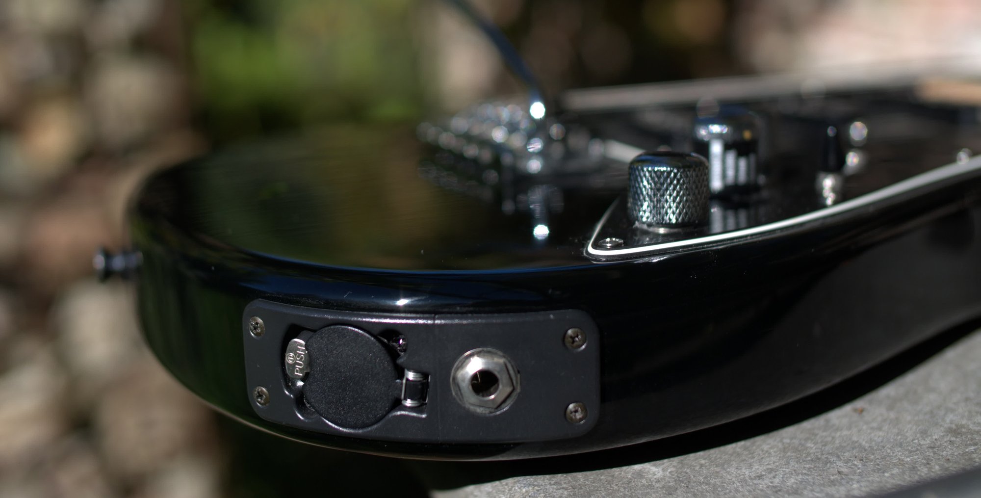
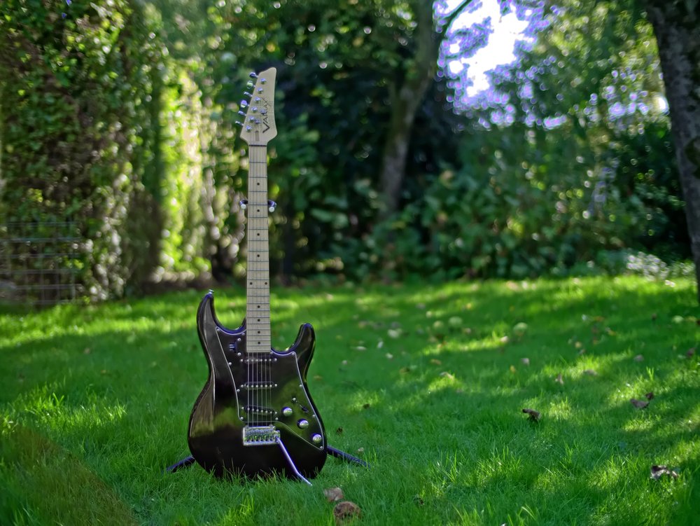
The Variax guitars are an "old" series of modelling guitars from Line6. The early models don't even feature any magnetic pickups since all the sound comes from piezo pickups in the bridge. The guitar actually has a piezo pickup for every string which gives it the ability to do good pitch-shifting and modelling. At least a lot better than the modellers I've used.
I've known about these guitars since getting my first Line6 guitar effects unit that had a very interesting connection on the back. The effects unit I got was a Pod XT (somewhere in 2014) and on the back it had an ethernet jack marked "Variax".
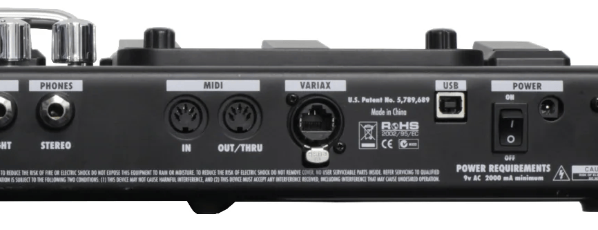
According to the manual this allowed connecting a Variax guitar and when using that the entire signal path from the guitar to the Pod was digital instead of using the ADC in the Pod after a long cable. I've always thought it would be a good idea to move the converters into the guitar since the pickups produce a pretty weak signal and converters are cheap now but apparently Line6 actually did that. Sadly the guitars were pretty expensive though.
Now 12 years later I got one secondhand and finally get to play with one of them.
This thing works great as a standalone guitar, for this you'd have to put their propriatary li-ion battery in it and then the analog output jack acts like a regular active guitar. But since I first got my Pod XT I have upgraded to the rackmount Pod X3 Pro so I wanted to finally use these two things together.
For this I got a short EtherCON cable. These are just normal ethernet cables but the plugs have a shell around them to make them lock like XLR connectors instead of having the clip on them to clock the ethernet jack.
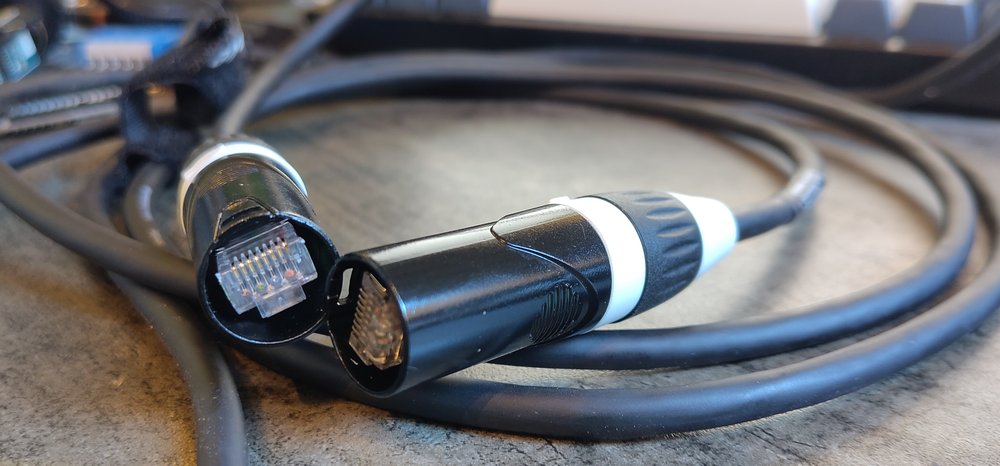
All together it worked.... fine...
The X3 does not have the most intuitive user interface and adding a Variax guitar doesn't make it easier. In fact it seems like I need to manually edit all the factory presets to make it actually pick a Variax model for the built-in presets. The Variax capable Line6 modellers also all have the issue of not fitting in the official Line6 Variax guitar carry case so the only solution left is... I build it myself...
The electrical interface
The nice thing about this is that I'm not the first person to mess with this so there's already some documentation around the digital interface. A great reference has been the vguitarforums which has a few great threads with information: https://www.vguitarforums.com/smf/index.php?topic=13484.0
Most importantly there's this diagram that has been posted in many spots talking about the VDI interface:
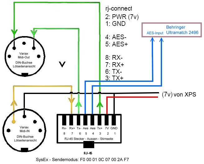
This combined with https://line6.com/technical-schematics/ which has schematics for various Variax guitars and VDI-capable modellers gave me enough information to build my own interface.
The idea was to build this around the Teensy 4.1 and basically copy most of the FOSDEM audio mixer for the analog parts and add the VDI port to it. The Teensy can easily accept the AES3 digital audio on the s/pdif input pin after it has been unbalanced and the library for the Teensy also has everything I'd need to do the MIDI parts.
I also modified the part of the schematic that normally generated +48V for microphone phantom power to generate the +7.5V power for the guitar instead.
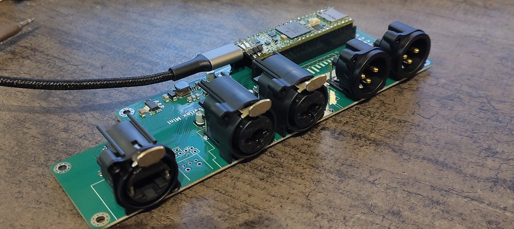
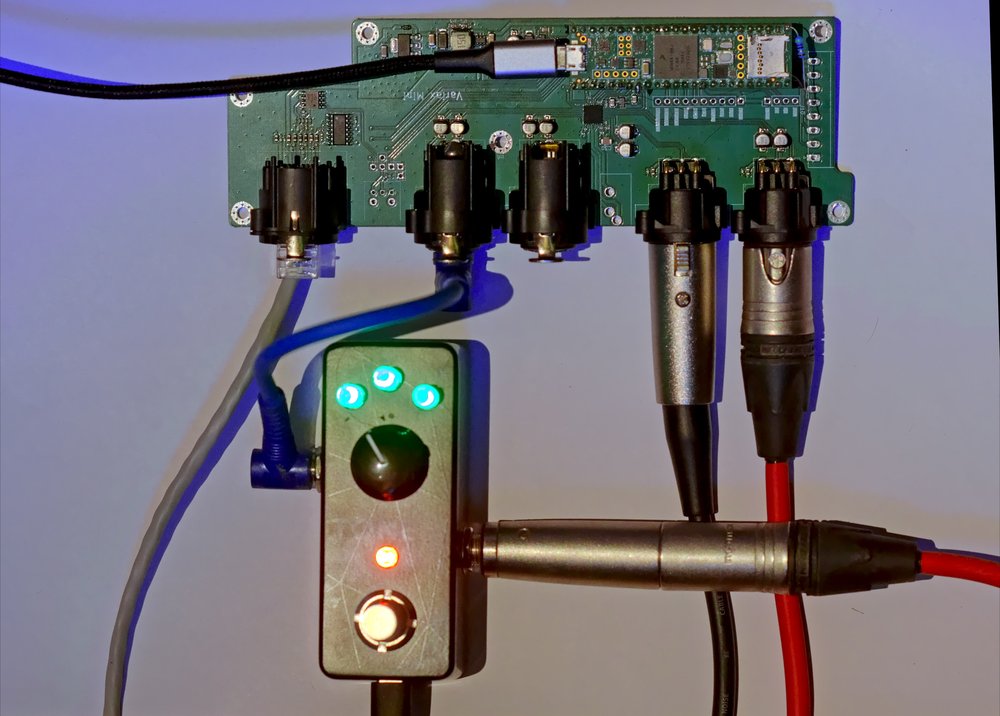
The result is the PCB above, two balanced analog inputs, two balanced analog outputs. The EtherCON jack for the guitar and still unpopulated in the picture above is the optical toslink connector that I want to use to send the signal digitally to my audio interface, and between the XLR jacks there's an unpopulated 3.5mm headphone jack.
Audio hardware mistakes
So getting this hardware running has been quite painful, mainly do to me making a few very stupid mistakes.
The first one is that I forgot the pull-up resistors on the i2c bus so the codec was not communicating. That was fixed easily by putting a few resistors on the back of the Teensy headers to pull up the lines.
The second mistake was more painful, I accidentally swapped the TX and RX pair for the MIDI signal on the guitar. This doesn't seem to have an easy way to work around on this PCB so I ended up not using my EtherCON cable for this at all but instead using a regular ethernet cable where I swapped the midi pairs on.
The biggest mistake though is the messed up i2s bus. I did not route mclk to the codec which causes quite a bit of issues since the clock recovery from bclk on the codec is not great, especially since I also did not get the impedance matching for the bus right so it has a lot of reflections. I now have a bodge wire connecting the 11Mhz mclk signal through a 50Ω resistor to the right pin on the codec and that has made the audio quality bearable at least.
I think with this together I've found all the major hardware issues I've created so that can very easily be fixed for a second revision board if I feel like throwing away $300 again to produce a second one.
Routing audio
The way audio is handled is pretty much the opposite of the Pod series. Instead of picking a patch on the Pod and maybe the guitar following that setting I'm actually making my board switch patches based on the guitar model selected on the Variax.
The plan for how audio is routed is pretty simple, when I'm on an accoustic model the audio should be routed through directly to one of the XLR outputs so it can go to my audio interface and then my headphones (or a full range speaker). I'm also using freeverb on the teensy to add a bit of reverb to this.
When selecting an electric model the audio is routed to the second XLR output instead which then goes through my electric guitar rig and finally returns to the XLR input where it is mixed back into the full range XLR output using the analog passthrough of this codec. In this case my guitar rig is just the ToneX one pedal that apparently can switch presets over USB so that might be something I implement in the future.
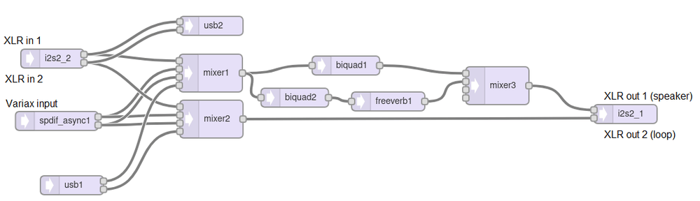
The current setup in the Teensy is pretty simple. The inputs are routed to mixers so I can select and blend various inputs to the main output. Then there's two EQ banks for the main output, one doing the main EQ and the other removes a bit of bass from the sound before going through the reverb. Finally mixer3 blends the reverb sound and the dry sound together for the XLR output.
What's not pictured here is the sound of XLR in 2 also being mixed into XLR out 1 directly in the codec with the volume for that path controlled by the preset switching logic.
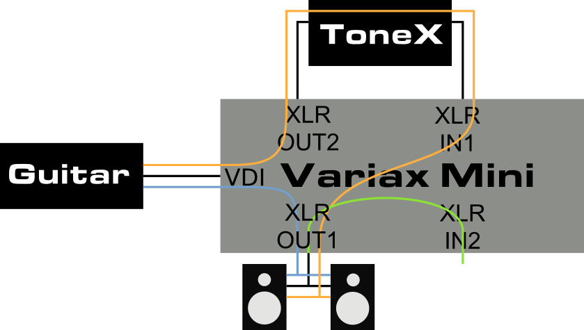
The blue path here visualizes the routing when an accoustic model is selected and the orange path is selected when an electric guitar model is being used. The green path is always active to route in AUX audio into the output, or could be used to also run a microphone through the reverb path.
MIDI Control protocol
For the control part of the guitar I'm going to need to actually reverse engineer a bit more myself. The protocol is MIDI and the basics are available online but I'm interested in a few more complicated features. I want to have the board load in the preset information from the guitar on bootup like the Line6 PC software can so I don't have to hardcode a list of preset mappings in my firmware. I also want to load the custom tunings that are set on the tuning wheel since I just can't remember what I stored in what slot so I need to put it on a display.
The initial thing I did for testing is create an USB midi interface on the teensy and link that to the hardware midi port I've created. Suprisingly this is enough for the Line6 Workbench HD software to recognize the guitar and start the configuration for it. Sadly just like using the X3 the software just doesn't work and crashes the guitar when changing settings...
Variax Workbench HD
I've added a debugger to the Teensy firmware that dumps the midi communication to the serial port so I can see what the Workbench software is doing in realtime. All the communication here is MIDI sysex vendor commands except the initial connection sequence where the Identity Request/Reply messages are used from the MIDI standard.
PC  -> 7E 7F     06 01 (Identity Request)
VDI <- 7E 7F     06 02 00 01 0C 07 00 05 00 30 32 32 33 (Identity Reply)
PC  -> 00 01 0C  03 10 00
PC  -> 00 01 0C  03 0F 00
PC  -> 7E 7F     06 01 (Identity Request)
VDI <- 7E 7F     06 02 00 01 0C 07 00 05 00 30 32 32 33 (Identity Reply)
PC  -> 00 01 0C  07 05 2A 01 (Wakeup?)
PC  -> 00 01 0C  07 05 18 00 00
VDI <- 00 01 0C  07 05 01
Then the software does 60 requests for the 60 presets slots available
PC  -> 00 01 0C  07 05  21  00 09 0C 0C 00 00 00 0B 0C 0C 00 00 00
VDI <- 00 01 0C  07 05  21  00 09 0C 0C 00 00 00 0B 0C 0C 00 00 00 0C 0C 0C 00 00 00 2E 10 03 00 00 00 00 70
PC  -> 00 01 0C  07 05  21  01 09 0C 0C 00 00 00 0B 0C 0C 00 00 00
VDI <- 00 01 0C  07 05  21  01 09 0C 0C 00 00 00 0B 0C 0C 00 00 00 0C 0C 0C 00 00 00 1A 44 33 00 00 00 00 70
PC  -> 00 01 0C  07 05  21  02 09 0C 0C 00 00 00 0B 0C 0C 00 00 00
VDI <- 00 01 0C  07 05  21  02 09 0C 0C 00 00 00 0B 0C 0C 00 00 00 0C 0C 0C 00 00 00 52 09 4E 00 00 00 00 10
According to timing it seems like the data responded here is enough to show both the preset slot name in the software and the details about the guitar but there just doesn't seem to be enough bytes different between these slots to actually encode all that. It might just be a reference into a list of stock presets that are stored.
There's also a big packet sent when you change guitar models in one of the slots that seems large enough that it might actually loading DSP code into it. After increasing my sysex buffer size a few times and then switching to a streaming approach it seems like the models are 6KB large and sending them is the part that make the guitar crash until rebooted. This makes it very hard to actually reverse engineer more of the format.
The other thing I looked into is the custom tunings, which I did manage to modify using the official software. So here's a dump for the response of the various tuning slots:
VDI: 1B 01   00 00 00 00 00 00   00 00 00 00 00 00   00 00 00 00 00 00   00 00 00 00 00 00   00 00 00 00 00 00   00 00 00 00 00 00       01 04 04 05 03 05 01 04 04 04 0E 04 00 02 04 04 02 05 00 02 00 02 00 02 00 02 00 02 00 02 00 02 00 02 00 02
VDI: 1B 02   00 00 00 00 00 00   00 00 00 00 00 00   00 00 00 00 00 00   00 00 00 00 00 00   00 00 00 00 00 00   0B 0A 0A 0A 0A 0E       0F 04 02 05 04 04 04 04 00 02 00 05 00 02 00 02 00 02 00 02 00 02 00 02 00 02 00 02 00 02 00 02 00 02 00 02
VDI: 1B 03   05 05 05 05 05 0F   05 05 05 05 05 0F   05 05 05 05 05 0F   05 05 05 05 05 0F   05 05 05 05 05 0F   05 05 05 05 05 0F       0C 04 01 04 08 04 04 04 00 02 06 04 0E 04 07 05 0F 04 00 02 00 02 00 02 00 02 00 02 00 02 00 02 00 02 00 02
VDI: 1B 04   05 05 05 05 05 0F   05 05 05 05 05 0F   05 05 05 05 05 0F   05 05 05 05 05 0F   05 05 05 05 05 0F   00 00 00 00 00 0E       0F 04 02 05 04 04 04 04 00 02 00 05 00 02 00 02 02 06 00 02 00 02 00 02 00 02 00 02 00 02 00 02 00 02 00 02
VDI: 1B 05   0B 0A 0A 0A 0A 0E   0B 0A 0A 0A 0A 0E   0B 0A 0A 0A 0A 0E   0B 0A 0A 0A 0A 0E   0B 0A 0A 0A 0A 0E   0B 0A 0A 0A 0A 0E       05 04 0E 04 0F 04 0F 04 04 04 00 02 00 02 0E 04 07 05 00 02 00 02 00 02 00 02 00 02 00 02 00 02 00 02 00 02
VDI: 1B 06   0B 0A 0A 0A 0A 0E   0B 0A 0A 0A 0A 0E   00 00 00 00 00 00   00 00 00 00 00 00   00 00 00 00 00 00   0B 0A 0A 0A 0A 0E       04 04 01 04 04 04 04 04 01 04 07 04 00 02 00 02 00 02 00 02 00 02 00 02 00 02 00 02 00 02 00 02 00 02 00 02
VDI: 1B 07   0B 0A 0A 0A 0A 0E   0B 0A 0A 0A 0A 0E   05 05 05 05 05 0F   00 00 00 00 00 00   00 00 00 00 00 00   0B 0A 0A 0A 0A 0E       05 04 00 05 0F 04 04 04 00 02 0E 04 00 02 00 02 00 02 00 02 00 02 00 02 00 02 00 02 00 02 00 02 00 02 00 02
VDI: 1B 08   00 00 00 00 00 00   0B 0A 0A 0A 0A 00   00 00 00 00 00 00   0B 0A 0A 0A 0A 0E   0B 0A 0A 0A 0A 0E   06 05 05 05 05 0D       05 06 00 07 0F 04 03 04 00 02 0E 06 01 06 0D 06 00 02 02 07 0F 06 0A 06 00 02 00 02 00 02 00 02 00 02 00 02
VDI: 1B 09   0A 0A 0A 0A 0A 02   0A 0A 0A 0A 0A 02   0A 0A 0A 0A 0A 02   0A 0A 0A 0A 0A 02   0A 0A 0A 0A 0A 02   05 05 05 05 05 01       00 07 01 06 03 04 04 03 00 02 0F 06 02 07 04 06 00 02 00 02 00 07 0F 06 0E 06 05 07 04 07 07 06 0E 06 09 06
VDI: 1B 0A   00 00 00 00 00 00   0B 0A 0A 0A 0A 0E   00 00 00 00 00 0E   05 05 05 05 05 0F   00 00 00 00 00 00   00 00 00 00 00 00       05 04 00 05 0F 04 01 04 00 02 0E 04 00 02 00 02 00 02 00 02 00 02 00 02 00 02 00 02 00 02 00 02 00 02 00 02
VDI: 1B 0B   06 05 05 05 05 0D   06 05 05 05 05 0D   06 05 05 05 05 0D   06 05 05 05 05 0D   06 05 05 05 05 0D   06 05 05 05 05 0D       03 07 0D 02 03 04 0E 06 01 06 04 07 02 07 01 06 04 06 00 02 00 02 04 06 00 02 00 02 00 02 00 02 00 02 00 02
                                                                                                                                         03 07 00 02 01 04 0E 06 01 06 04 07 02 07 01 06 04 06 00 02 00 02 04 06 00 02 00 02 00 02 00 02 00 02 00 02
The first 36 bytes seem to encode the actual pitch shifting offsets of the string which is a number in the range of -12 to +12 for every string. I can't think of a reason why they decided to encode a number that fits into a single byte into 6 bytes per string instead...
The rest of the data seems to encode the name of the custom tuning although the text encoding scheme is very weird. On the last line the same name is returned again but the second character is changed from to - (I think the stored name was C Standard but as you can see in the comparison it's two bytes that have changed, the third and the fifth one.
03 07 0D 02 03 04 0E 06 01 06 04 07 02 07 01 06 04 06 00 02 00 02 04 06 00 02 00 02 00 02 00 02 00 02 00 02
03 07 00 02 01 04 0E 06 01 06 04 07 02 07 01 06 04 06 00 02 00 02 04 06 00 02 00 02 00 02 00 02 00 02 00 02
The number encoding for the string offsets is also weird. The 25 possible options I can set using the software are:
-12  01 00 00 00 00 08
-11  0B 0A 0A 0A 0A 08
-10  06 05 05 05 05 09
-9   01 00 00 00 00 0A
-8   0B 0A 0A 0A 0A 0A
-7   06 05 05 05 05 0B
-6   00 00 00 00 00 0C
-5   0B 0A 0A 0A 0A 0C
-4   06 05 05 05 05 0D
-3   00 00 00 00 00 0E
-2   0B 0A 0A 0A 0A 0E
-1   05 05 05 05 05 0F
0    00 00 00 00 00 00
1    0B 0A 0A 0A 0A 00
2    05 05 05 05 05 01
3    00 00 00 00 00 02
4    0A 0A 0A 0A 0A 02
5    05 05 05 05 05 03
6    00 00 00 00 00 04
7    0A 0A 0A 0A 0A 04
8    05 05 05 05 05 05
9    0F 0F 0F 0F 0F 05
10   0A 0A 0A 0A 0A 06
11   05 05 05 05 05 07
12   0F 0F 0F 0F 0F 07
At least there seem to be some sort of pattern in it but I can't figure out what the logic behind it is.
I have enough of the protocol that I can at least show the tuning info on a display and currently I have a hardcoded mapping in the firmware from model preset slot number to model name and routing settings until I figure out more of the protocol.
First I need to make an actual case for the thing so the bodge wires don't break while I'm debugging software. Also getting the actual display and the rest of the connectors will help for this. But I think I will save that for a future blog post.