
Pictures of boards are everywhere when you work in IT. Lots of computer components come as (partially) bare PCBs and single board computers are also a popular target. Taking a clear picture of a PCB is not trivial though. I suspect a lot of these product pictures are actually 3d renders.
While updating hackerboards I noticed not all boards have great pictures available. I have some of them laying around and I have a camera... how hard could it be?
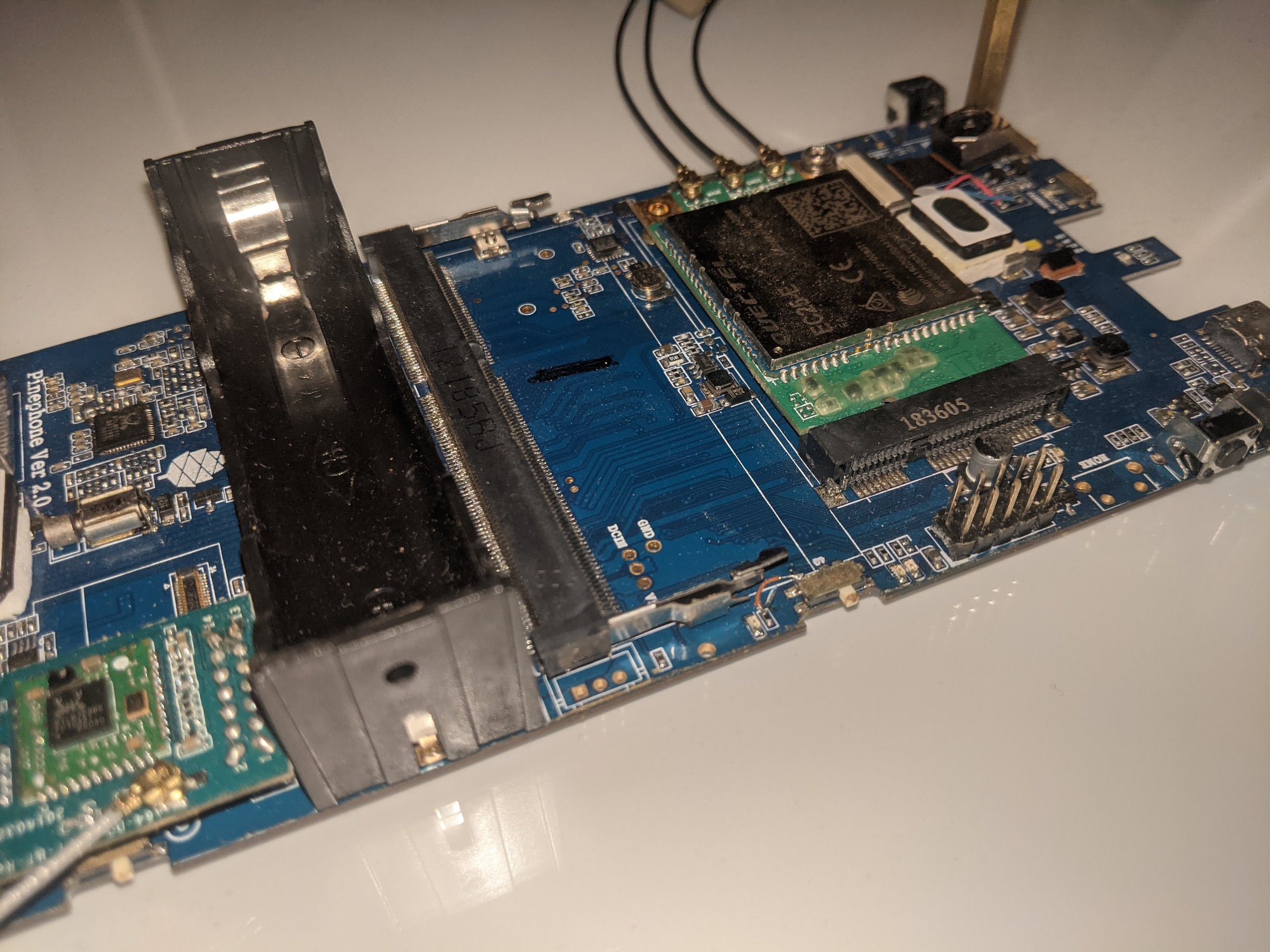
Definitely the worst picture is the one in the header above. Taken with a phone at an angle with the flash in bad lighting conditions. I've taken quite a bunch of pictures of PINE64 boards, like some of the pictures in the header of the pine64 subreddit and the picture in the sidebar. I've had mixed results with taking the pictures but the best results I've had with taking board pictures is using an external flash unit.
The ideal setup

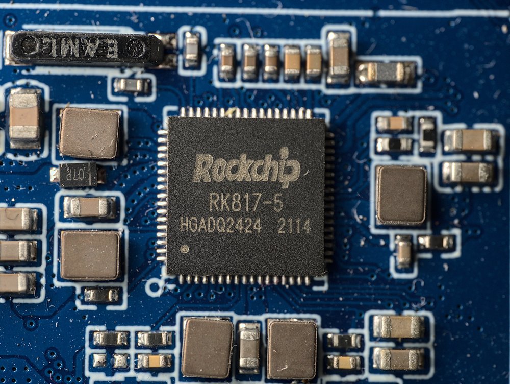
So to create a great picture I've decided to make a better setup. I've used several components for this. The most important one is two external flashes controlled with a wireless transmitter. I've added softboxes to the flashers to minimize the sharp shadows usually created when using a flash. This produces quite nice board pictures with even lighting.
For all the pictures from this setup I've used a 50mm macro lens. Not only is it great for getting detail pictures of the small components, it's also the lens with the least distortion I have. Having less distortion in the lens is required to have a sharp picture all the way to the edges of the board and not have the edges of the board look curved. The curvature can be fixed in software but the focal plane not being straight to the corners can't be fixed.
It's possible to get even less shadows on the board by using something like a ring light, while this gets slightly more clarity I also find this just makes the pictures less aesthetically pleasing.
So how to deal with the edges of the board? For a lot of website pictures you'd want a white background. I have done this by just using a sheet of paper and cleaning up the background using photo editing software. This is quite time consuming though. The usual issues with this is that the background is white but not perfectly clipped to 100% pure white in the resulting picture. There's also the issue of the board itself casting a slight shadow.
I took my solution for this from my 3D rendering knowledge (which is not much). You can't have a shadow on an emitter. To do this in the real world I used a lightbox.
Lightboxes are normally for tracing pictures and are quite easy to get. It doesn't give me a perfectly white background but it gets rid of the shadows at least.

To get this from good to perfect there's another trick though. If I take a picture without the flashes turned on but everything else on the same settings I get a terribly underexposed picture... except for the background.

All I need to do to get a clean background is increasing the contrast of this picture to get a perfect mask. Then in gimp I can just overlay this on the picture with the layer mode set to lighten only.

It's also possible to use the mask picture as the alpha channel for the color picture instead. This works great if there's a light background on the website, it shows the flaws though when the website has a dark background.
Let's create the worst-case scenario and use a pure black background:

Now edges are visible on the cutouts. Due to the mismatch in light color temperature with the light box the edges are also blue here. A lot of edges can be fixed by running the dilate filter in gimp on the mask layer to make the mask crop into the board by one pixel. it makes the holes in the board too large though. To get this perfect manual touchup is still required.
Automating it further
Now the input data is perfect enough that I can make the cutout with a few steps in gimp it's also possible to automate this further with the magic of ImageMagic.
$ convert board.jpg \( mask.jpg \
		-colorspace gray \
		-negate \
		-brightness-contrast 0x20 \
	\) \
	-compose copy-opacity \
	-composite board.png
This loads the normal picture from board.jpg and the backlit picture as mask.jpg and composites them together into a .png with transparency.
But it can be automated even further! I still have a bit of camera shake from manually touching the shutter button on the camera and I need to remember to take both pictures every time I slightly nudge the device I'm taking a picture of.
The camera I'm using here is the Panasonic Lumix GX7. One of the features of this camera is the built-in wifi. Using this wifi connection it's possible to use the atrocious Android application to take pictures and change a few settings.
After a bit of reverse engineering I managed to create a Python module for communicating with this camera. Now I can just script these actions:
import time
from remotecamera.lumix import Lumix

# My camera has a static DHCP lease
camera = Lumix("192.168.2.41")
camera.init()

camera.change_setting('flash', 'forcedflashon')
camera.capture()
time.sleep(1)
camera.change_setting('flash', 'forcedflashoff')
camera.capture()
Now I can just run the script and it will take the two pictures I need. It's probably also possible to fetch the images over wifi and automatically trigger the compositing but it sadly requires changing the wifi mode on the camera itself between remote control and file transfer.
Not just for PCBs
This setup is not only useful for PCB pictures. This is pretty great for any product picture where the product fits on the lightbox.

Here's the composite of a SHIFT 6mq. Pictures of the screen itself are still difficult due to the pixel pattern interfering with the pixels of the camera sensor and the display reflecting the light of the flashes. This can probably be partially fixed once I get a polarizing filter that fits this lens.