
Network switches are simple devices, packets go in, packets go out. Luckily people have figured out how to make it complicated instead and invented managed switches.
Usually this is done by adding a web-interface for configuring the settings and see things like port status. If you have more expensive switches then you'd even get access to some alternate interfaces like telnet and serial console ports.
There is a whole second category of managed switches though that people don't initially think of. These are the network switches that are inside consumer routers. These routers are little Linux devices that have a switch chip inside of them, one or more ports are internally connected to the CPU and the rest are on the outside as physical ports.
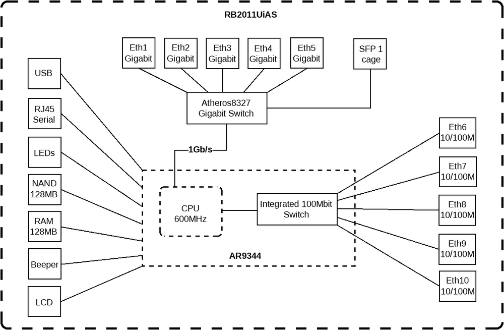
Here is an example of such a device that actually has this documented. I always thought that the configuration of these switch connected ports was just a nice abstraction by the webinterface but I was suprised to learn that with the DSA and switchdev subsystem in Linux these ports are actually fully functioning "local" network ports. Due to this practically only being available inside integrated routers It's pretty hard to play around with unfortunately.
What is shown as a single line on this diagram is actually the connection of the SoC of the router and the switch over the SGMII bus (or maybe RGMII in this case) and a management bus that's either SMI or MDIO. Network switches have a lot of these fun acronyms that even with the full name written out make little sense unless you know how all of this fits together.
Controlling your standard off-the-shelf switch using this system simply isn't possible because the required connections of the switch chip aren't exposed for this. So there's only one option left...
Making my own gigabit network switch
Making my own network switch can't be that hard right? Those things are available for the price of a cup of coffee and are most likely highly integrated to reach that price point. Since I don't see any homemade switches around on the internet I guess the chips for those must be pretty hard to get...
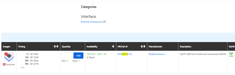
Nope, very easy to get. There's even a datasheet available for these. So I created a new KiCad project and started creating some footprints and symbols.
I'm glad there's any amount of datasheet available for this chip since that's not usually the case for Realtek devices, but it's still pretty minimal. I resorted to finding any devices that has schematics available for similar Realtek chips to find out how to integrate it and looking at a lot of documentation for how to implement ethernet in a design at all.
The implementation for the chip initially looked very complicated, there's about 7 different power nets it requires and there are several pretty badly documented communication interfaces. After going through other implementations it seem like the easiest way to power it is just connect all the nets with overlapping voltage ranges together and you're left with only needing a 3.3V and 1.1V regulator.
The extra communication busses are for all the extra ports I don't seem to need. The switch chip I selected is the RTL8367S which is a very widely used 5-port gigabit switch chip, but it's actually not a 5-port chip. It's a 7 port switch chip where 5 ports have an integrated PHY and two are for CPU connections.
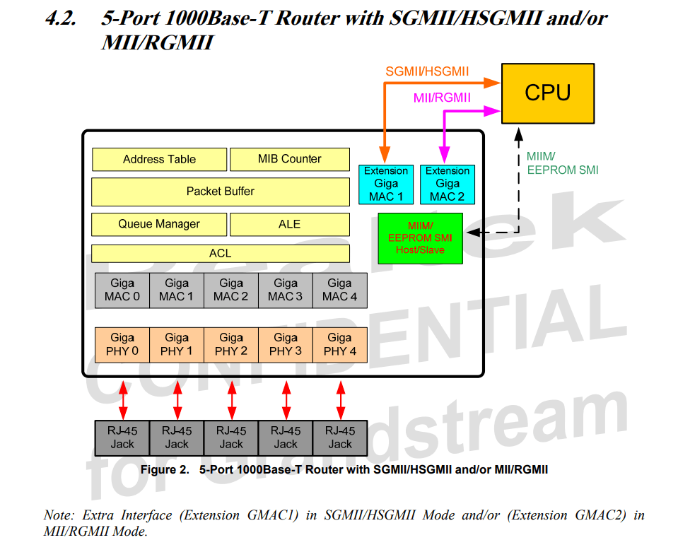
My plan is different though, while there are these CPU ports available there is actually nothing in the Linux switchdev subsystem that requires the CPU connection to be to those ports. Instead I'll be connecting to port 0 on the switch with a network cable and as far as the switchdev driver knows there's no ethernet PHY in between.
The next hurdle is the configuration of the switch chip, there's several configuration systems available and the datasheet does not really describe what is the minimum required setup to actually get it to function as a regular dumb switch. To sum up the configuration options of the chip:
- There's 8 pins on the chip that are read when it's starting up. These pins are shared with the led pins for the ports so that makes designing pretty annoying. Switching the setting from pull-up to pull-down also requires the led to be connected in the different orientation.
- There's an i2c bus that can be connected to an eeprom chip. The pins for this are shared with the SMI bus that I require to make this chip talk to Linux though. There is pin configuration to select from one of two eeprom size ranges but does not further specify what this setting actually changes.
- There's a SPI bus that supports connecting a NOR flash chip to it. This can store either configuration registers or firmware for the embedded 8051 core depending on the configuration of the bootup pins. The SPI bus pins are also shared with one of the CPU network ports.
- There is a serial port available but from what I guess it probably does nothing at all unless there's firmware loaded in the 8051.
My solution to figuring out is to just order a board and solder connections differently until it works. I've added a footprint for a flash chip that I ended up not needing and for all the configuration pins I added solder jumpers. I left out all the leds since making that configurable would be pretty hard.
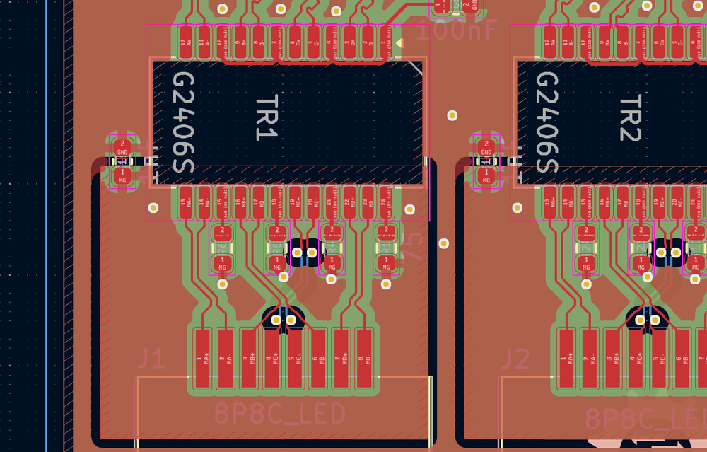
The next step is figuring out how to do ethernet properly. There has been a lot of documentation written about this and they all make it sound like gigabit ethernet requires perfect precision engineering, impedance managed boards and a blessing from the ethernet gods themselves to work. This does not seem to match up with the reality that these switches are very very cheaply constructed and seem to work just fine. So I decided to open up a switch to check how many of these coupling capacitors and impedance matching planes are actually used in a real design. The answer seems to be that it doesn't matter that much.
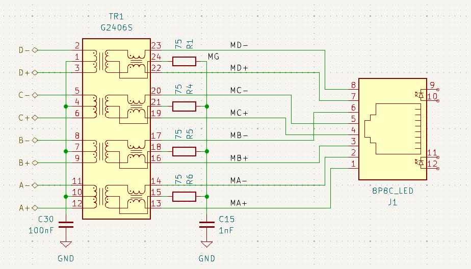
This is the design I have ended up with now but it is not what is on my test PCB. I got it almost right the first time though :D
The important parts seem to be matching the pair skew but matching the length of the 4 network pairs is completely useless, this is mainly because network cables don't have the same twisting rate for the 4 pairs and so the length of these are already significantly different inside the cable.
The pairs between the transformer and the RJ45 jack has it's own ground plane that's coupled to the main ground through a capacitor. The pairs after the transformer are just on the main board ground fill.
What I did wrong on my initial board revision was forgetting the capacitor that connects the center taps of the transformer on the switch side to ground making the signals on that side referenced to board ground. This makes ethernet very much not work anymore so I had to manually cut tiny traces on the board to disconnect that short to ground. In my test setup the capacitor just doesn't exist and all the center taps float. This seems to work just fine but the final design does have that capacitor added.
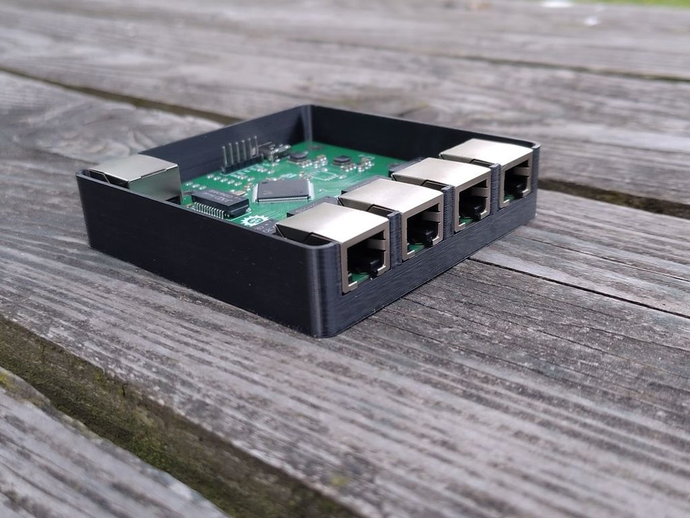
The end result is this slightly weird gigabit switch. It has 4 ports facing one direction and one facing backwards and it is powered over a 2.54mm pinheader. I have also added a footprint for a USB Type-C connector to have an easy way to power it without bringing out the DuPont wires.
Connecting it to Linux
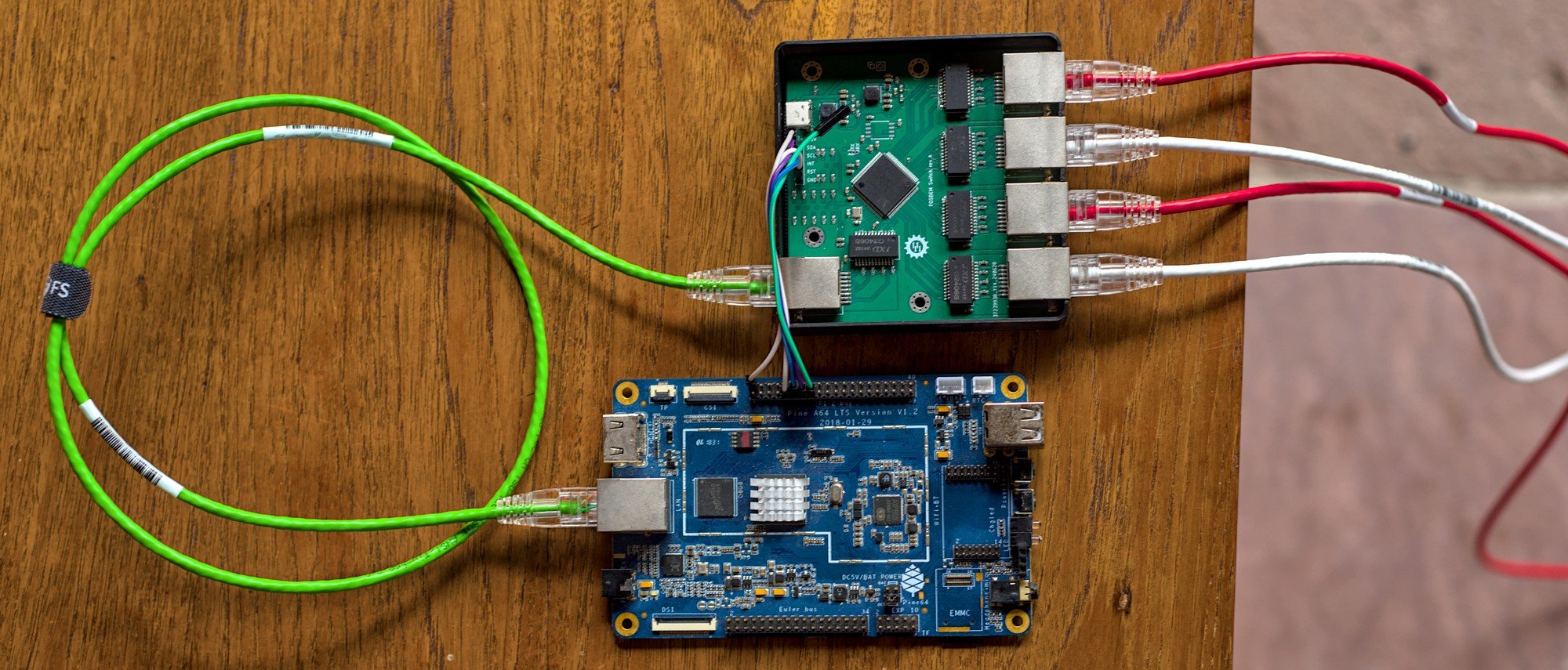
For my test setup I've picked the PINE64 A64-lts board since it has the connectors roughly in the spots where I want them. It not being an x86 platform is also pretty important because configuration requires a device tree change, can't do that on a platform that doesn't use device trees.
The first required thing was rebuilding the kernel for the board since most kernels simply don't have these kernel modules enabled. For this I enabled these options:
CONFIG_NET_DSAfor the Distributed Switch Architecture systemCONFIG_NET_DSA_TAG_RTL8_4for having port tagging for this Realtek switch chipCONFIG_NET_SWITCHDEVthe driver system for network switchesCONFIG_NET_DSA_REALTEK,CONFIG_NET_DSA_REALTEK_SMI,CONFIG_NET_DSA_REALTEK_RTL8365MBfor the actual switch chip driver
Then the more complicated part was figuring out how to actually get this all loaded. In theory it is possible to create a device tree overlay for this and get it loaded by U-Boot. I decided to not do that and patch the device tree for the A64-lts board instead since I'm rebuilding the kernel anyway. The device tree change I ended up with is this:
diff --git a/arch/arm64/boot/dts/allwinner/sun50i-a64-pine64-lts.dts b/arch/arm64/boot/dts/allwinner/sun50i-a64-pine64-lts.dts
index 596a25907..10c1a5187 100644
--- a/arch/arm64/boot/dts/allwinner/sun50i-a64-pine64-lts.dts
+++ b/arch/arm64/boot/dts/allwinner/sun50i-a64-pine64-lts.dts
@@ -18,8 +18,78 @@ led {
gpios = <&r_pio 0 7 GPIO_ACTIVE_LOW>; /* PL7 */
};
};
+
+switch {
+ compatible = "realtek,rtl8365rb";
+ mdc-gpios = <&pio 2 5 GPIO_ACTIVE_HIGH>; // PC5
+ mdio-gpios = <&pio 2 7 GPIO_ACTIVE_HIGH>; // PC7
+ reset-gpios = <&pio 8 5 GPIO_ACTIVE_LOW>; // PH5
+ realtek,disable-leds;
+
+ mdio {
+ compatible = "realtek,smi-mdio";
+ #address-cells = <1>;
+ #size-cells = <0>;
+
+ ethphy0: ethernet-phy@0 {
+ reg = <0>;
+ };
+
+ ethphy1: ethernet-phy@1 {
+ reg = <1>;
+ };
+
+ ethphy2: ethernet-phy@2 {
+ reg = <2>;
+ };
+
+ ethphy3: ethernet-phy@3 {
+ reg = <3>;
+ };
+
+ ethphy4: ethernet-phy@4 {
+ reg = <4>;
+ };
+ };
+
+ ports {
+ #address-cells = <1>;
+ #size-cells = <0>;
+
+ port@0 {
+ reg = <0>;
+ label = "cpu";
+ ethernet = <&emac>;
+ };
+
+ port@1 {
+ reg = <1>;
+ label = "lan1";
+ phy-handle = <ðphy1>;
+ };
+
+ port@2 {
+ reg = <2>;
+ label = "lan2";
+ phy-handle = <ðphy2>;
+ };
+
+ port@3 {
+ reg = <3>;
+ label = "lan3";
+ phy-handle = <ðphy3>;
+ };
+
+ port@4 {
+ reg = <4>;
+ label = "lan4";
+ phy-handle = <ðphy4>;
+ };
+ };
+};
};
It loads the driver for the switch with the realtek,rtl8365rb, this driver supports a whole range of Realtek switch chips including the RTL8367S I've used in this design. I've removed the CPU ports from the documentation example and just added the definitions of the 5 regular switch ports.
The important part is in port@0, this is the port that is facing backwards on my switch and is connected to the A64-lts, I've linked it up to &emac which is a reference to the ethernet port of the computer. The rest of the ports are linked up to their respective PHYs in the switch chip.
In the top of the code there's also 3 GPIOs defined, these link up to SDA/SCL and Reset on the switch PCB to make the communication work. After booting up the system the result is this:
1: lo: <LOOPBACK> mtu 65536 qdisc noop state DOWN qlen 1000
    link/loopback 00:00:00:00:00:00 brd 00:00:00:00:00:00
2: eth0: <BROADCAST,MULTICAST> mtu 1508 qdisc noop state DOWN qlen 1000
    link/ether 02:ba:6f:0c:21:c4 brd ff:ff:ff:ff:ff:ff
3 lan1@eth0: <BROADCAST,MULTICAST,M-DOWN> mtu 1500 qdisc noop state DOWN qlen 1000
    link/ether 02:ba:6f:0c:21:c4 brd ff:ff:ff:ff:ff:ff
4 lan2@eth0: <BROADCAST,MULTICAST,M-DOWN> mtu 1500 qdisc noop state DOWN qlen 1000
    link/ether 02:ba:6f:0c:21:c4 brd ff:ff:ff:ff:ff:ff
5 lan3@eth0: <BROADCAST,MULTICAST,M-DOWN> mtu 1500 qdisc noop state DOWN qlen 1000
    link/ether 02:ba:6f:0c:21:c4 brd ff:ff:ff:ff:ff:ff
6 lan4@eth0: <BROADCAST,MULTICAST,M-DOWN> mtu 1500 qdisc noop state DOWN qlen 1000
    link/ether 02:ba:6f:0c:21:c4 brd ff:ff:ff:ff:ff:ff
I have the eth0 device here like normal and then I have the 4 interfaces for the ports on the switch I defined in the device tree. To make it actually do something the interfaces actually need to be brought online first:
$ ip link set eth0 up
$ ip link set lan1 up
$ ip link set lan2 up
$ ip link set lan3 up
$ ip link set lan4 up
$ ip link
1: lo: <LOOPBACK> mtu 65536 qdisc noop state DOWN qlen 1000
    link/loopback 00:00:00:00:00:00 brd 00:00:00:00:00:00
2: eth0: <BROADCAST,MULTICAST,UP,LOWER_UP> mtu 1508 qdisc mq state UP qlen 1000
    link/ether 02:ba:6f:0c:21:c4 brd ff:ff:ff:ff:ff:ff
3: lan1@eth0: <NO-CARRIER,BROADCAST,MULTICAST,UP> mtu 1500 qdisc noqueue state LOWERLAYERDOWN qlen 1000
    link/ether 02:ba:6f:0c:21:c4 brd ff:ff:ff:ff:ff:ff
4: lan2@eth0: <NO-CARRIER,BROADCAST,MULTICAST,UP> mtu 1500 qdisc noqueue state LOWERLAYERDOWN qlen 1000
    link/ether 02:ba:6f:0c:21:c4 brd ff:ff:ff:ff:ff:ff
5: lan3@eth0: <BROADCAST,MULTICAST,UP,LOWER_UP> mtu 1500 qdisc noqueue state UP qlen 1000
    link/ether 02:ba:6f:0c:21:c4 brd ff:ff:ff:ff:ff:ff
6: lan4@eth0: <NO-CARRIER,BROADCAST,MULTICAST,UP> mtu 1500 qdisc noqueue state LOWERLAYERDOWN qlen 1000
    link/ether 02:ba:6f:0c:21:c4 brd ff:ff:ff:ff:ff:ff
Now the switch is up you can see I have a cable plugged into the third port. This system hooks into a lot of the Linux networking so it Just Works(tm) with a lot of tooling. Some examples:
- Add a few of the lan ports into a standard Linux bridge and the switchdev system will bridge those ports together in the switch chip so Linux doesn't have to forward that traffic.
- Thinks like
ethtool lan3just work to get information about the link. and withethtool -S lan3all the standard status return info which includes packets that have been fully handled by the switch.
Limitations
There's a few things that makes this not very nice to work with. First of all the requirement of either building a custom network switch or tearing open an existing one and finding the right connections.
It's not really possible to use this system on regular computers/servers since you need device trees to configure the kernel for this and most computers don't have kernel-controlled GPIO pins available to hook up a switch.
As far as I can find there's also no way to use this with a network port on the computer side that's not fixed, USB network interfaces don't have a device tree node handle to refer to to set the conduit port.
There is a chance some of these limitations are possible to work around, maybe there's some weird USB device that exposes pins on the GPIO subsystem, maybe there's a way to load switchdev without being on an ARM device but that would certainly take a bit more documentation...