
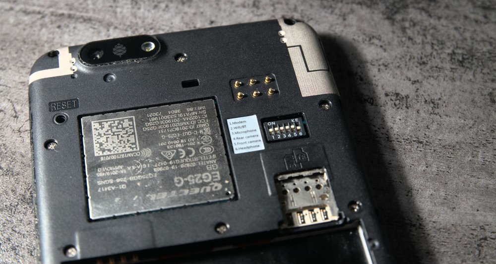
So one of the features of the PinePhone that hasn't seen much (any?) use is the pogo pin expansion header on the back. It's 6 pogo pins that can be used to make backcovers that extend the phone functionality.
These pogo pins give external access to battery power, usb power, a dedicated i2c bus and an interrupt pin. This is enough to make a wide range of custom attachments. The official announced attachments are a battery extension backcover (that uses the two power pins) and a keyboard backcover (that uses the i2c bus).
Making your own extension
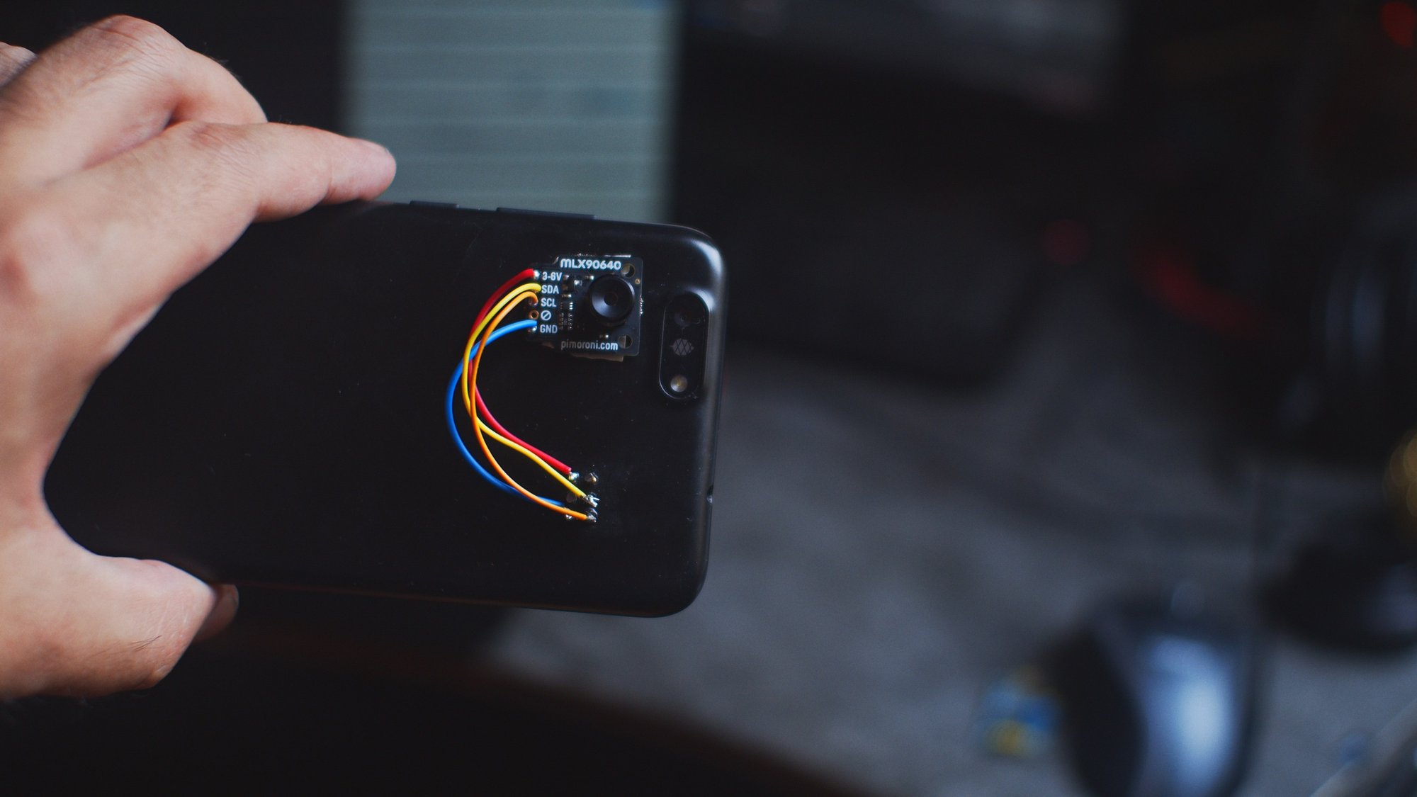
Since this is an open platform, it's quite easy to make your own extension that connects to the PinePhone pogo pins. In my case I'm going to attach an MLX90640 far-infrared thermal array, which is a fancy way of saying thermal camera. It's a module that can be get relatively cheap, but it's low resolution. The sensor only has 32x24 pixels, to get a good image that has to be upscaled and combined with a visible light camera (which conveniently is built into the PinePhone) to create a nice thermal image.
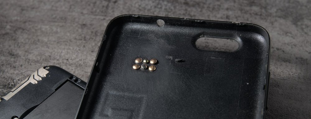
To make the physical interface, I melted 6 holes through a PinePhone backcover and put tiny nails in them that match up with the pogo pins.
I also made a video showing me doing this. Then I used some double sided tape to stick the thermal camera module to the backcover and soldered wires between the sensor and the nails. The pinout for the pogo pins is this:
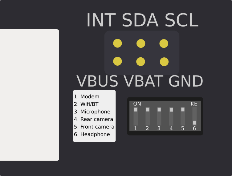
Connecting up an i2c device should be relatively straightforward, it's important to note that the i2c lines are pulled up by the phone to 3v3.
The VBUS pin is powered by USB, I used this one for the sensor, it only has power when something is plugged into USB, and it's 5V.
The second power pin is VBAT, which connects to the battery voltage.
What can you do with this?
Everything! The sky is the limit! except bandwith and power constraints ofcourse...
The maximum speed of the i2c bus is 400 kHz, which is enough for a lot of applications, but don't expect to add ethernet or hdmi to this. Since i2c is a bus you can add multiple things at the same time to these pins. I just added the single thermal camera but you can just add a second i2c device to the same pins in parallel.
If you need another bus than i2c you can probably get a bridge chip for it or add a small microcontroller to bridge another protocol. Basically any microcontroller has support for i2c and can most likely connect to whatever you want, like use gpio on the microcontroller to read from a keyboard matrix, or add some IR leds and sensors to add IrDA.
The software side
There are two ways to use your newly attached gadget. The first is i2cdev. It isn't super efficient but it gives you access to the i2c hardware directly from userspace. The only thing that's needed is modprobe i2cdevto make /dev/i2c* appear. The bus on the pogopins on the PinePhone is twi2, so /dev/i2c-2 should be the right bus.
Here's a simple python example for reading a byte from and attached i2c chip:
from smbus2 import SMBus

# Connect to /dev/i2c-2
bus = SMBus(2)

# Read register 0x42 from the i2c device at address 0x33
bus.write_byte_data(0x33, 0, 0x42)
value = bus.read_byte_data(0x33, 0)
The second method is letting a kernel module deal with the hardware. This can be accomplished by recompiling the dtb/kernel with your hardware in it, which isn't very portable. Or by using device tree overlays.
Here's an example of the dtbo for an TI HDC1000 humidity and temperature sensor:
// Definitions for dhc1000 module
/dts-v1/;
/plugin/;

/ {
fragment@0 {
	// Target the pogo pin i2c bus
	target = <&i2c2>;
	__overlay__ {

		// Define the hdc100x device on this i2c bus
		hdc100x@40 {
			compatible = "ti,hdc1000";
			reg = <0x40>;
		};

	};
};
The loading of this device tree overlay is more complicated. It needs to be compiled first, which needs the sources of the kernel used on the PinePhone so it knows what &i2c2 means. Then the compiled dtbo file needs to be put somewhere in sysfs to make it load at runtime, or needs to be added to u-boot to be loaded at boot time. This is all a bit out of scope for this article (meaning I haven't tried it yet)
After the dtbo is loaded, the new device should just show up in the kernel like it was always part of the phone, in this example it's an iio sensor so it shows up in /sys/bus/iio/device:$number/$parameter, so you can just query the humidity by reading some file.
Connecting a thermal camera
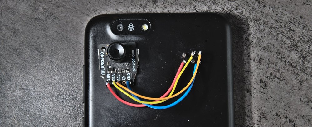
One of the things I have had here in my parts bin is the MLX90640 thermal imaging sensor. I thought it would make for a great demo of what's possible with the pogo pins. Connecting it was trivial since it only needs power and i2c on the breakout board I have and this breakout board also has a voltage regular so I can power it by anything from 3 to 6 volts, perfect for the PinePhone.
For the software side I chose the i2cdev method and used python to get data from the sensor. Only after a while I found out that there's already a kernel module available in the mainline kernel that exposes this sensor as a regular v4l2 webcam.
The first python lib I tried was the Adafruit circuitpython one, I didn't manage to get this to work since it expects if you're running it on Linux that it's must be a raspberry pi. Then I found a module from Seeed studio which seemed easier but still didn't give me any data from the sensor after messing with it for a while. It turns out the seeed and adafruit code is very similar and probably copied from eachother and had the interfacing code replaced.
Since both libraries weren't working I wrote a quick 'n dirty python script based on the registermap in the datasheet of the sensor and managed to get the raw sensor data from that. This code doesn't read the factory calibration data yet from the sensors eeeprom so there's quite a lot of variance in the pixels. The raw data from the pixels is also 16 bit signed data, which I just pick the 8 most significant bits from to make a simple grayscale png as output. Since somewhere around room temperature these raw values go negative there's some pure white pixels instead of useful data.
The raw data from the sensor looks a bit underwhelming, it's mainly messed up by not applying calibration which should get rid of the checkerboard pattern and the data format which should get rid of the white pixels.
The sensor actually responds with 2 extra rows of "pixels", this data is the extra data needed to get proper measurements from this like the global gain of the chip (since it does auto exposure) and the ambient chip temperature. With that data the absolute temperature for every pixel can be calculated.
For getting real nice "FLIR-like" output from this it should also be combined with the image captured from the way higher resolution normal camera in the PinePhone itself.
Conclusion
Is this demo practical? not really, the camera works but since it's quite bulky the phone can't be put in your pocket anymore. This can probably be solved by using a 3d printed backcover instead that properly integrates the camera and keeps it aligned with the visible light camera. This also needs a lot more software work to make it a nice experience.
It does provide a great demo of the extendability though and I can't wait to see what people will do with this feature.