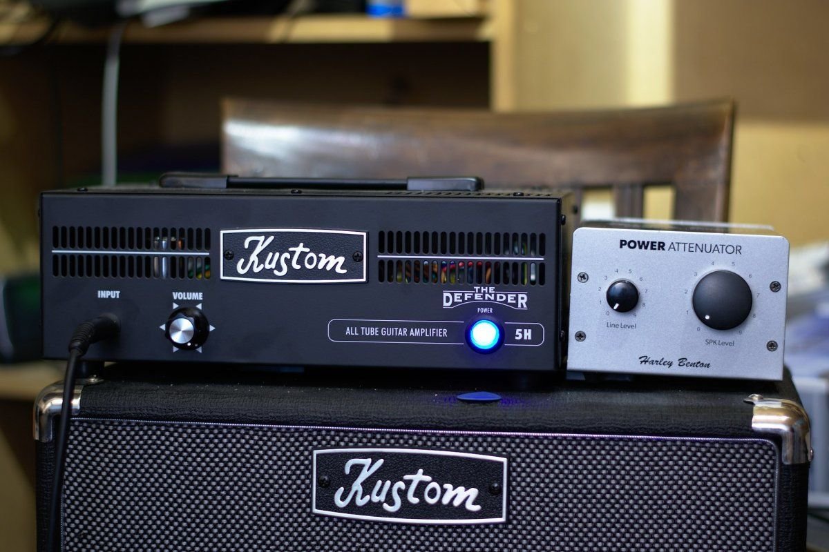
Thomann just started shipping their new Harley Benton Power Attenuator. It can handle an input power of
80 watts (it contains an 100 watt L-pad, so they added some margin). It is a simple device containing
only passive components. It has a control for cabinet volume and line-out volume but they are not fully
seperated. The line-out level is a signel tapped of after the main cabinet volume knob so you can't
turn the cabinet completely off and use the line out for recording / headset usage.


Measurement
To measure the performance of the attenuator I connected it to a USB DAC/ADC and ran a frequency sweep with the
tool QLoud. QLoud is a tool normally used to measure the frequency response of a speaker using a measurement microphone.
I connected the line out signal of the DAC to the 16 Ohm speaker input of the attenuator and connected the
speaker output of the attenuator to the line in of the USB DAC. I also did a reference measurement by
connecting the input and output of my DAC/ADC directly together. The last set of measurements is connecting
the line signal to the input of my guitar tube amp (a Defender 5H 15 watt all-tube amp) and connecting the
line-out of the attenuator to the USB ADC.

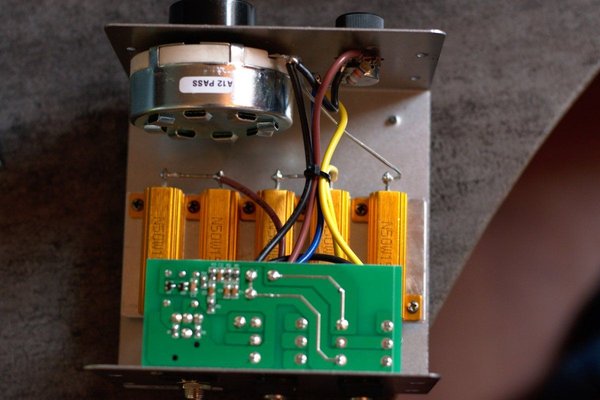
Taking it apart
I'm also curious what is inside a fully passive device for ~100 euro so I took it apart. The case is
very easy to open, 4 screws on the front and 4 on the back and you can just lift the side and top part off.
The answer to my question: there is not a lot in it.
The main part of the attenuator is the 100 watt L-pad (The huge potentiometer behind the cabinet volume knob).
The signal from the amp is put almost directly accross the two outer pins of the potmeter so it will dissipate
most of the energy. The other large part of the circuit is a bunch of 50 watt resistors (The resistors with
orange cooling fins). They are there to match the impedance for the amp. The signal coming from the L-pad pot
and the small potmeter for line-out is put straight into the line-out and speaker-out jack on the PCB. The rest
of the circuit on the PCB is for the MicMod circuit that is supposed to simulate a cabinet and provide a balanced
microphone signal. I haven't tested the MicMod output yet.