
There's a project called LCD Smartie that converted a character LCD into a small status monitor for your computer. It can show system status, the info on what's playing in Winamp. E-mail headlines.
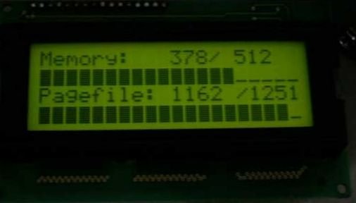
I wanted to have something similar, but connected to my fileserver to show some stats, but I didn't want to have yet another permanent light on my desk, it's already a chrismas lightshow of blue, green and orange power and status lights for various devices.
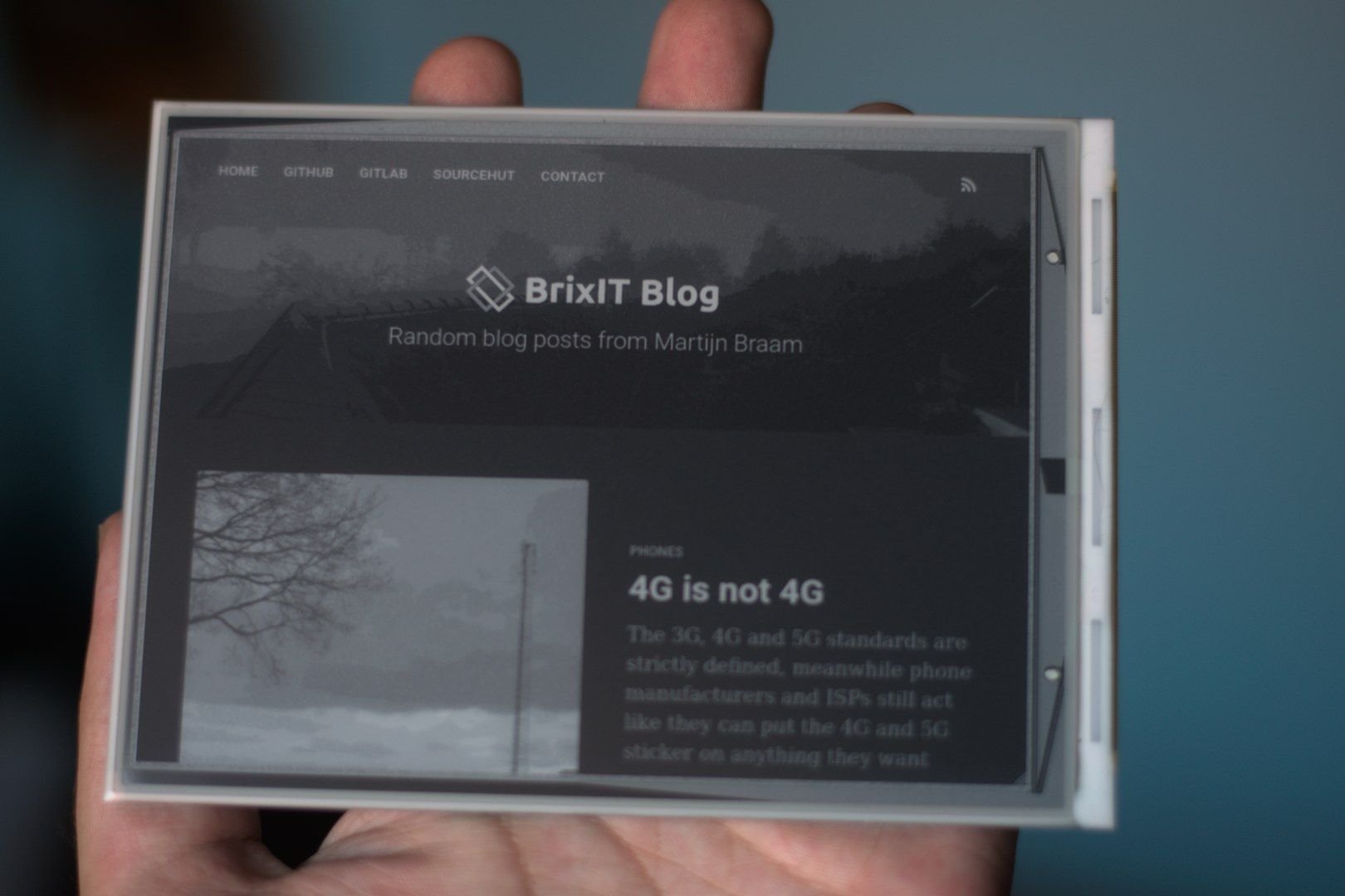
The nice solution for this would be using an e-paper display instead of an LCD. After some searching I found the 6" display kit with raspberry pi hat from Waveshare.
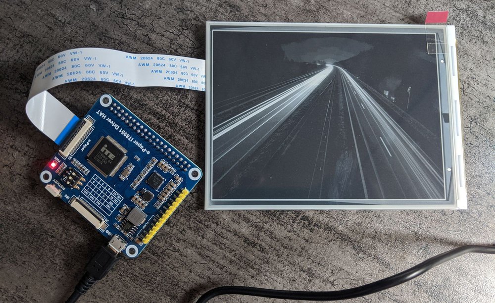
The nice thing about this specific board is that it also has a microUSB port for connecting it to a computer instead of a raspberry pi. Sadly there isn't really a lot of information available about this interface, it's designed to be driven by spi, i2c or i80 and the docs reflect that. The USB port seems to be mainly for updating firmware.
Waveshare has a Windows tool available that can communicate with the display controller over USB and upload firmware, it can also send images to it with their clunky interface. I want to control it with Linux though so I have to write something new.
The USB interface is pretty weird. The display shows up as a mass storage device with no medium inserted (like an SD card reader with no card inserted). Somehow their software can communicate with this. So the first step is sysinternals procmon. This is basically equivelent to running a strace in Windows.
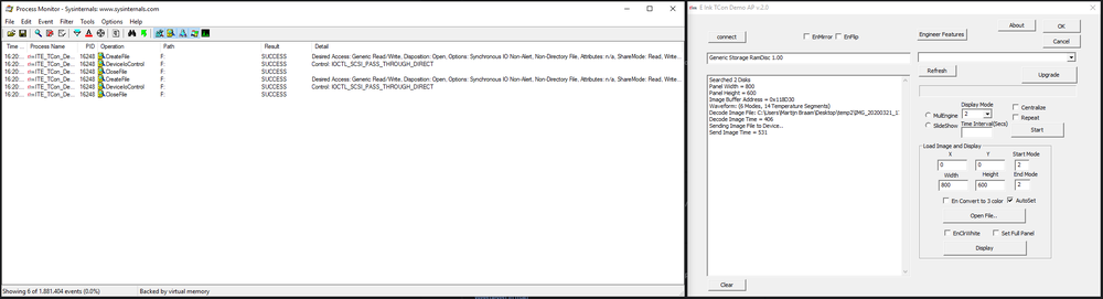
This shows it's opening the virtual mass storage device from the display controller (F: in my case) and then using IOCTL_SCSI_PASS_THROUGH_DIRECT to actually control the display.
This is the same communication protocol used by tools like smartmontools to communicate with harddisk firmware to get disk information. So the upside is that it should be possible to control this display without messing with kernel modules. The downside is that it will require root to control the display.
With this information I was finally able to find a datasheet that had some details on the USB communication protocol called "IT8951 USB Programming Guide" This contains some details on how the protocol works and some demo code for making these calls in Windows. Armed with this information I started writing a C program that should draw to the display.
The drawing procedure is pretty simple. You send a command to get some general information like the resolution and the address of the framebuffer. Then you use the load image command to send pixels to a specific part of the framebuffer, then you use the display command to actually trigger the display refresh. This is the part that makes the display flicker and show the new content.
It was all pretty straightforward except that it didn't work. My display just didn't start flickering to update the contents. After scanning through the datasheet for a while I gave up and went back to reverse engineering the Windows tool. This time I used Wireshark to make a dump of all the USB traffic since procmon didn't show me the actual data in the syscalls.
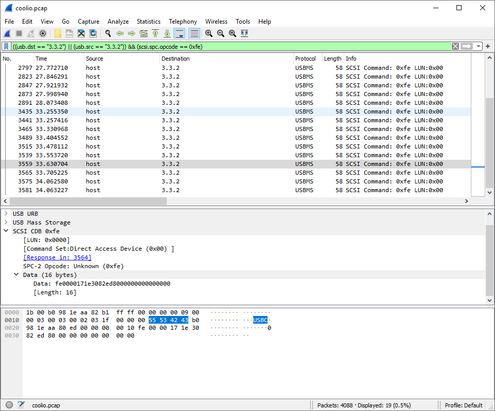
This did show some interesting things. Mainly that I was missing a single byte in the display update command (0x94) causing the display controller to hang until it was reset. Another interesting thing I noticed is that for uploading a full-screen image (800x600) it was sending the image in strips of 800x76 pixels using seperate load-image commands and then sending a single display-image command to update the whole screen. After implementing this I was able to update my e-paper over USB from Linux!
All this is available as a simple small tool: it8951 (named after the controller used). It takes a device name, x+y coordinates and the image width,height to update on the screen and then takes raw image data on stdin to display. The nice thing about this controller is that you don't have to care at all about low level image formatting, just send a 8-bit grayscale image to it and it will be converted in the right format to the display.
This display supports multiple modes (selected by the -m argument of my tool). Mode 0 is used to completely blank a region. It will flicker a few times and then make the region perfectly white.
The next one is Mode 2, it will display a 16 level grayscale image based on the 256 level input image you gave it, it will not do any dithering for this. Updating the screen in this mode will cause it to flicker that region once. This is called G16 mode.
The other nice mode is Mode 4, it is called A2 mode and will update the screen without flickering. It is very fast but it has a downside, it only renders pure black and white.

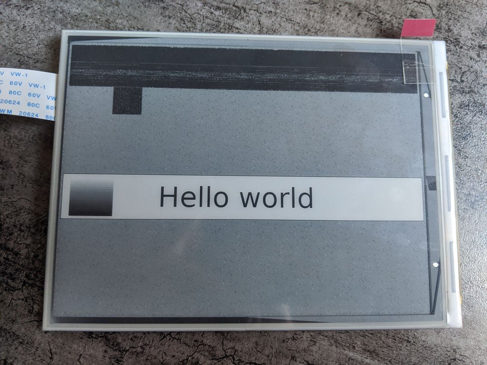
In the example above the date is drawn in G16 mode, since it's not updated often anyway and the time is drawn in A2 mode so it can update every minute without having an annoying flicker. You can see that the date has smoother edges since it can be anti-aliased using the 16 grayscale levels, The time has crispy edges since it's only pure black. Also the A2 move leaves some ghosting behind as you can see.
Drawing something useful
Now I have the display working with a tool I can pipe data into I made a python program that uses PIL to generate a nice status display. It generates a full screen background image that has the dates and the borders on them and draws that every day at midnight with a fresh date. It also uses this moment to fully clear the display in mode 0 to get rid of ghosting artifacts. Then it will update the time every minute in A2 mode in the center. It will then check all the data feeds and if one changed it will update only that specific region in G16 mode, which is distracting, but at that point it will also notify you that there's new data. When the python script is restarted it will update all the regions one by one, which looks very satisfying.