I'm certainly not the first person making a camera from a Raspberry Pi. Over the years I've seen several projects coming across my feeds that make various types of camera from the Pi since the first camera module was introduced. Generally these were first simple 3d printed enclosures for the raspberry pi without any display and just the camera module in front making a very simple digital point and shoot camera.
There's a few more advanced projects like CinePi that does high quality video recording with a Pi, mostly focussed on recording raw video. I've also seen PiDSLR that makes a camera that is actually a mirrorless camera not a DSLR (since it doesn't have the mirror part that makes it a DSLR).
What I haven't seen is something that does an end-to-end solution for using a Raspberry Pi as a broadcast/studio/streaming camera. I'm not entirely sure what the correct terminology is.
The goal is to have a camera that outputs frames over HDMI as with low latency so it can be hooked into the video mixing system for live streaming. This is used for example for live streaming events, where normally to keep costs down either photography cameras are (ab)used as video cameras or actual expensive video cameras are rented.
Picking hardware
Going for the Raspberry Pi was the obvious choice. There's not something magical about this specific hardware except that there's actually documentation available on how to use the video subsystems of this hardware. Specifically I'm using the picamera2 python module to do deal with talking to libcamera to configure the camera here.
I used the Raspberry Pi 4B 2GB here since this is the first generation of Pi that is not horrifically slow, which is super useful when dealing with video. It also is a slightly better board for this than the Raspberry Pi 5 since this actually has the DSI display connected to the SoC instead of the pi1 which gives the display output some additional limitations on that hardware.
For the camera itself I picked the Raspberry Pi HQ Camera, mainly because it had HQ in the name, but also because it's the largest sensor they have available which will be super useful for lens selection later.
It's also possible to get larger third-party sensors, the nicest I've come across are the sensor boards made by Will Whang (The *Eye ones). He has made several camera boards that are significantly larger than the official Raspberry Pi ones, even to the point of having larger sensors than some of the high quality video cameras I have.
| Sensor | Size | Diagonal (at 16:9 crop) | Active size | Crop (at 1080p) |
|---|---|---|---|---|
| HQ Camera (imx477) | 1/2.3" | 7.90mm (7.24mm) | 6.3 x 3.6 | 5.7x (6.0x) |
| Pi Camera 3 (imx708) | 1/2.43" | 7.40mm (7.40mm) | 6.5 x 3.6 | 5.6x (6.7x) |
| Pi Camera 2 (imx219) | 1/4" | 4.59mm (4.21mm) | 3.7 x 2.1 | 9.8x (16.7x) |
| OneInchEye (imx283) | 1" | 15.86mm (15.13mm) | 13.2 x 7.4 | 2.7x (3.9x) |
| StarlightEye (imx585) | 1/1.2" | 12.78mm (12.78mm) | 11.1 x 6.3 | 3.2x (3.2x) |
| FourThirdsEye (imx294) | 4/3" | 23.31mm (22.14mm) | 19.3 x 10.9 | 1.9x (2.0x) |
Here's a comparison of the official Pi cameras and The Will Whang ones. The main number I care about here is the cropfactor when the sensor is running in 1920x1080 resolution. It's not simply picking the largest sensor (as defined by the diagonal size in inches usually) since most of these sensors don't have a resolution that's a nice multiple of 1080p. You've probably noticed this before when using your phone and it zooms in significantly when you switch to video mode.
A good example of this is the Pi Camera v3, this sensor has almost exactly the same size as the HQ camera but the sensor resolution is higher. The HQ camera is 4072 pixels wide and the V3 camera is 4608 pixels wide. The closest multiple of 1920 that fits in these resolutions is 2x (3840) which means that in video mode I'm wasting 232 pixels on the HQ sensor but 768 pixels on the V3 sensor. This makes the final crop factor of the V3 camera much higher than just the size difference with the HQ camera.
Another thing that's a bit annoying with comparing these cameras for video use is that they differ in aspect ratio, which affects the size comparisons of these sensors. The HQ camera is a 4:3 sensor which means while it is a 1/2.3" sensor some of the pixels at the top and bottom will never be used for video since it gets cropped to 16:9. When taking that into account the sensor area of the V3 camera is actually larger than the HQ sensor (and it would be better if it wasn't for the cropping to get to 1080p resolution).
Ideally I'd be using either the StarlightEye or FourThirdsEye sensors for my design but those are hard to actually aquire, practically requiring me to produce the sensor boards myself. While that would be nice to try to figure out it would be a massive distraction to actually getting a functional camera first...
Lenses
The HQ camera module I have has a CS-mount for attaching lenses. This is a lens mount that is mostly used for security cameras which significantly limits the availability of actually sharp lenses.
To get started with the camera I ordered a CS mount security camera lens from ebay which is a 8-50mm f/1.4 zoom lens to give me a decent zoom range to test things with.
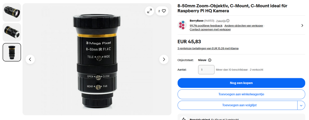
Even at the widest setting of 8mm the field of view with the HQ camera is not terribly wide. It's probably fine for live streaming talks at events since the camera is in the back of the room anyway, but it's already quite cramped to use at home when I don't want to have only my face in frame.
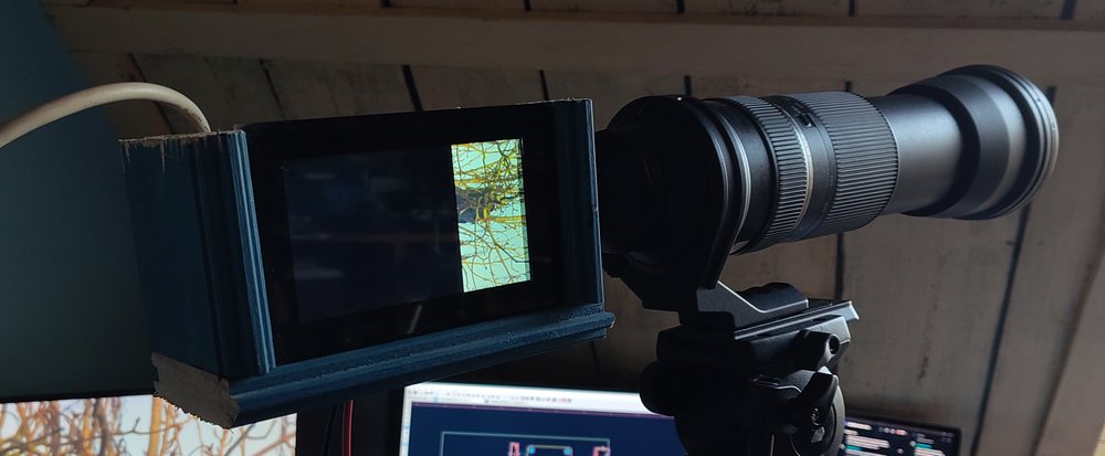
To test further I also now have a Tamrom 2.8-11mm lens on the way which should give me a bit more range and maybe some better quality than this "3 Mega Pixel" lens.
Another option is using an adapter to mount other optics to this camera. From previous experiments I already have a CS-to-F adapter which allows me to mount my Nikon lenses to this tiny sensor. The problem with this is the cropfactor making it very impractical to use. My 50mm prime lens with the 6x cropfactor already becomes an effective 300mm lens which is too much zoom for most usecases. Most of my F-mount lenses are also simply not that sharp anymore when you have this much cropping.
I did hook up my longest lens to this for fun though... This 600mm lens with a 6x cropfactor gives me a very nice 3.6 meter focal length...
The software
I expected to spend way more time here to get something working at all initially here. Initially I spend quite a bit of time trying to go through the libcamera c++ tutorial, but annoyingly that tutorial ends before any frames actually end up on the display. I tried reading how the frames up in the DRM subsystem from the the sources of the rpicam-vid application but that codebase has enough layers of indirection to make it very annoying to browse.
While figuring out how it all works I came across the picamera2 repository which is a Python wrapper around libcamera and pykms to do similar things to what the rpicam-vid application is doing. It even comes with actual proper documentation!
The last 3 days I've been messing around with this codebase to make it do what I want. The picamera2 package comes with a module for creating a DRM preview which I initially used to get a fullscreen video feed going out of the HDMI port of the camera but I had to drop that class and write my own based on it to deal with multimonitor usage which I need for the side display.
The side display
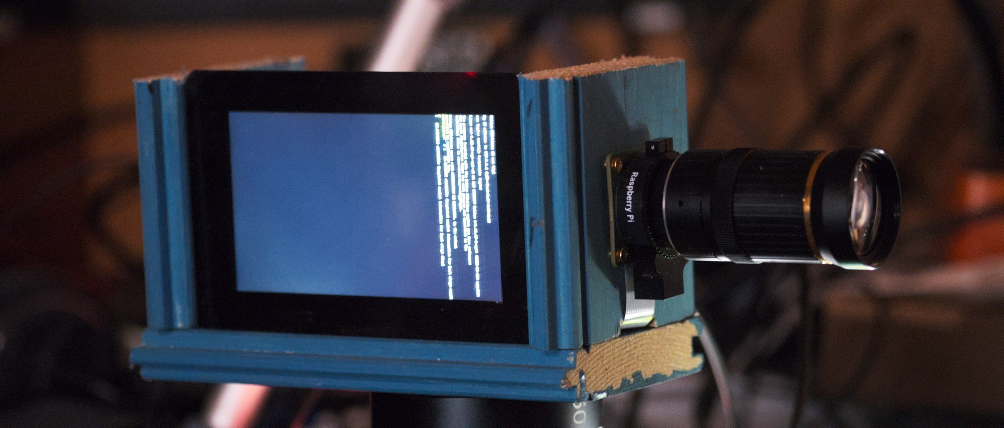
Speaking of side display, the formfactor for this prototype and my main UX inspiration is this the BMD Pyxis camera:
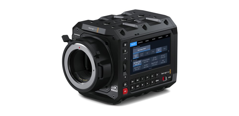
Having a display on the side would make it easier to have the camera on a tripod pushed all the way to the back wall of a room, where I usually get annoyed with my other cameras that I can't see the menus anymore. Also it's a nice box shape since I don't need the camera to pretend to be an old school DSLR for this.
For this side screen I have the official 5" touchscreen from Raspberry Pi. This shows the same video feed as what's going out of the HDMI output except it has the UI drawn over this. This runs nice and smooth thanks to the DRM/KMS subsystem in Linux dealing with all the hard things for me.
The Python application configures both outputs and requests a plane on both of them with a YUV format for displaying the camera feed. Both of these planes just receive the same DMABUF handle I get from libcamera and get the same video feed perfectly in sync without having to copy anything. The HDMI plane gets rendered at 1080p and on the display it's rendered at 720p to match the monitor resolution. All this scaling and color conversion is dealt with by the hardware video scaler blocks in the Pi4 SoC so doesn't really cost me any performance in userspace, leaving me plenty space to be inefficient by using Python.
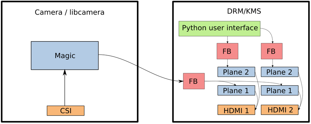
The code creates more than one plane per output though. On top of the YUV plane for the camera feed an overlay plane is created with an RGBA format that shows the UI overlay. This layer is a seperate framebuffer for each output and I generate my custom UI here by drawing it slowly with PIL and then pushing that buffer to libdrm when any of the UI state actually changes. Thanks to the planes the refresh rate for these things are completely decoupled. Even when I hit a debugger breakpoint in the UI thread of my application the camera feed happily keeps updating at 60fps behind my crashed application.
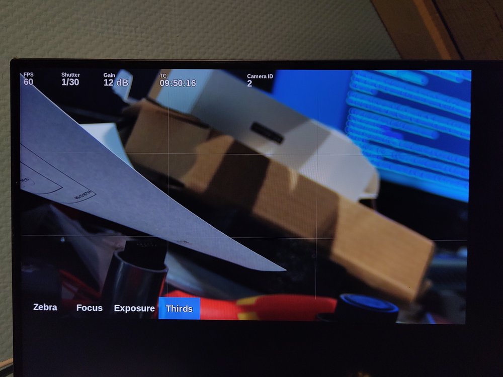
Here you can see the UI layer on top of the camera feed. For the monitoring/ui output I create even more layers between the camera plane and the UI plane. For this output the layers are:
- UI layer at the top
- Focus peaking overlay
- Exposure hint overlay
- Zebra overlay
- Camera plane
Where these planes get shown/hidden by setting the alpha attribute in DRM on these planes. The buttons on the bottom of this UI basically toggle these layers and there's some optimisation to not update the contents of these layers when they are hidden.
Streaming
I don't want the camera to be fully limited to just outputting the camera feed over HDMI. Luckily the Raspberry Pi has a hardware video encoder that actually works and the picamera2 module can easily set that up. Sadly using the hardware encoder means I have to drop the framerate of the camera to 30fps. Implementing this was extremely easy:
self.encoder = H264Encoder(self.config.encoder.bitrate_int)
self.stream = PyavOutput("rtsp://127.0.0.1:8554/cam", format="rtsp")
self.encoder.output = self.stream
self.cam.start_encoder(self.encoder)
Now the camera streams 10Mbps (default from my config) H.264 to localhost over RTSP. Then to actually make that stream useful I run mediamtx as a daemon which receives that stream and exposes it over various protocols.
Beyond the proof of concept
My initial design, while looking pretty ugly, does actually work great. There's a few annoying bits to fix which just involves a few hours being annoyed at the documentation. This is things like forcing the 1080p output on the HDMI connector so the whole thing doesn't break when you boot it without a monitor connected.
Also I need to figure out now how to generate a Raspbian image with my software in it, and ideally without a lot of other useless stuff in it. This is probably just a few creative invocations of debootstrap away.
Case design is something that does need a lot of work though. My initial idea is have some neat CNC machined enclosure for it to make it look professional. A modular box-camera design where there's a metal frame that allows 6 panels to be inserted into it:
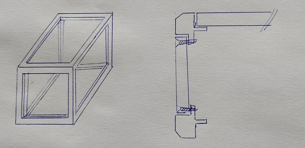
This way the frame can provide the sturdyness of the camera and the panels can just be 3D printed easily for prototyping. The bottom panel would probably be a metal or wooden panel to have a sturdy tripod mount and the front panel would probably be a CNC machined part anyway to have a lens mount in there.
The issue with this design is that I have no clue about actually designing anything like this, I barely can get enough CAD software working to make basic 3D prints and this would actually require knowing manufacturing. How many parts would that frame be split into to fabricate it cheaply?
Another solution is to use some sort of prefab case. Like extruded aluminium project cases, but those usually are smaller than what I'm designing here (100x100x150) and wouldn't solve the issue of mounting stuff to it.
Custom PCB design
To make the design complete this would also require a custom PCB. This can easily be done as a Compute Module 4 carrier board, which would also allow attaching 4-lane cameras which is needed for the larger sensors. My plan here is to make a board that includes full size HDMI adapters, an ethernet port, the stereo ADC chip from the FOSDEM audio board to get balanced audio inputs and possibly some motor drivers to easily make this a PTZ camera.
Another thing I'd like to do is put an RP2040 on the HDMI CEC line so it can listen for camera control commands from Blackmagic Design hardware to make it integrate a bit more neatly into the video production ecosystem. You might've seen a Camera ID already in the UI picture above where it says Camera 2. This is because I have half of this working already and it's plugged into input 2 of an ATEM mixer.
Maybe it would also be possible to have an usb-c port with HDMI-alt-mode support so modern touchscreens can be attached as UI as alternative to the built-in monitor.
The camera in action
So I also made a video about this project, it's a lot easier to show off a camera working on video than in a blog post :)
https://www.youtube.com/watch?v=otN7aUJbgck
If you want to run my code (or help developing this!) you can fetch it from git:
https://github.com/MartijnBraam/picam
I also really need to come up with a name for this project but haven't had any inspiration for it...