
Now I've written all the parts for the Phone Test Setup in the previous parts, it's time to make the first deployment.
For the postmarketOS deployment I'm running the central controller and mosquitto in a container on the postmarketOS server. This will communicate with a low-power server in a test rack in my office. The controller hardware is an old passively cooled AMD board in a 1U rack case. I sadly don't have any part numbers for the rack case since I got a few of these cases second hand with VIA EPIA boards in them.
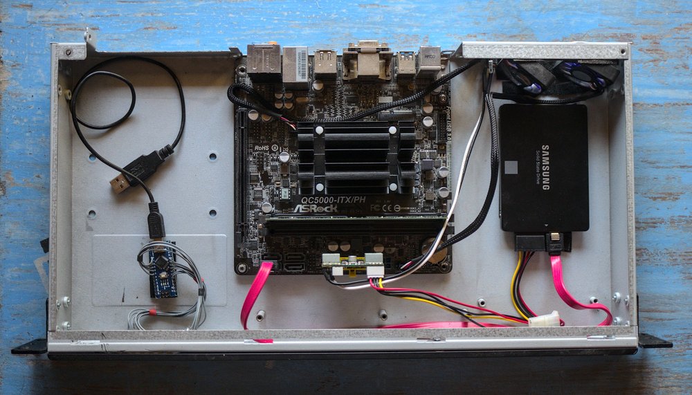
The specs for my controller machine are:
- AMD A4-5000 APU
- 4GB DDR3-1600 memory
- 250GB SSD
- PicoPSU
The specifications for the controller machine are not super important, the controller software does not do any cpu-heavy or memory-heavy tasks. The important thing is that it has some cache space for unpacking downloaded OS images and it needs to have reliable USB and ethernet. For a small setup a Raspberry Pi would be enough for example.
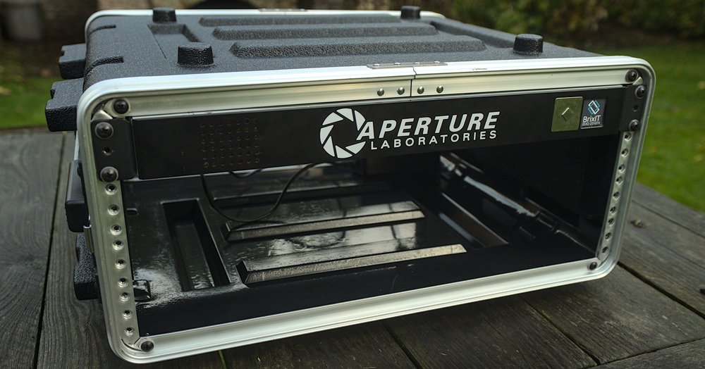
This server now sits in my temporary test rack for development. This rack will hold the controller PC and one case of test devices. This rack case can hold 8 phones in total by using 4 rack units.
Deploying the software
After running all the software for the test setup on my laptop for months I now started installing the components on the final hardware. This is also a great moment to fix up all the installation documentation.
I spend about a day dealing with new bugs I found while deploying the software. I found a few hardcoded values that had to be replaced with actual configuration and found a few places where error logging needed to be improved a lot. One thing that also took a bit of time is setting up Mosquitto behind an Nginx reverse proxy.
The MQTT protocol normally runs on plain TCP on port 1883 but since this involves sending login credentials its better to use TLS instead. The Mosquitto daemon can handle TLS itself and with some extra certificates will run on port 8883. This has the downside that Mosquitto needs to have access to the certificates for the domain and it needs to be restarted after certbot does its thing.
Since The TLS for the webapplication is already handled by Nginx running in reverse proxy mode it's easier to just set up Nginx to do reverse proxying for a plain TCP connection. This is the config that I ended up with:
stream {
  upstream mqtt_servers {
    server 10.0.0.107:1883;
  }
  server {
    listen 8883 ssl;
    proxy_pass mqtt_servers;
    proxy_connect_timeout 1s;

    ssl_certificate /etc/letsencrypt/.../fullchain.pem;
    ssl_certificate_key /etc/letsencrypt/.../privkey.pem;
    ssl_dhparam /etc/letsencrypt/ssl-dhparams.pem;
  }
}
Another thing that had to be done for the deployment is writing actual service files for the components. The init files now sets up openrc in my Alpine installations to supervise the components, deal with logging and make sure the database schema migrations are run on restart.
Putting together the phone case
To neatly store the phones for the test setup I decided to use a 2U rack case since that's just high enough to store modern phones sideways. For this I'm using a generic 2U rackmount project box with the very easy to remember product code G17082UBK. This is a very cheap plastic case with an actual datasheet.
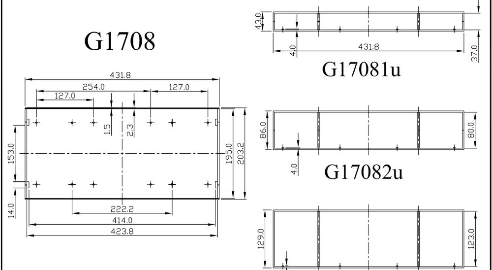
I used this documentation to design a tray that fits between the screw posts in this case. The tray is printed in three identical parts and each tray has three slots. I use dovetail mounts to have the phone holders slide on this tray.
All this is designed using OpenSCAD. I never liked 3D modelling software but with this it's more like programming the shapes you want. This appeals a lot to me since... I'm a software developer.
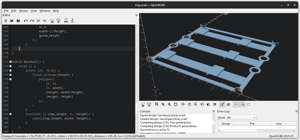
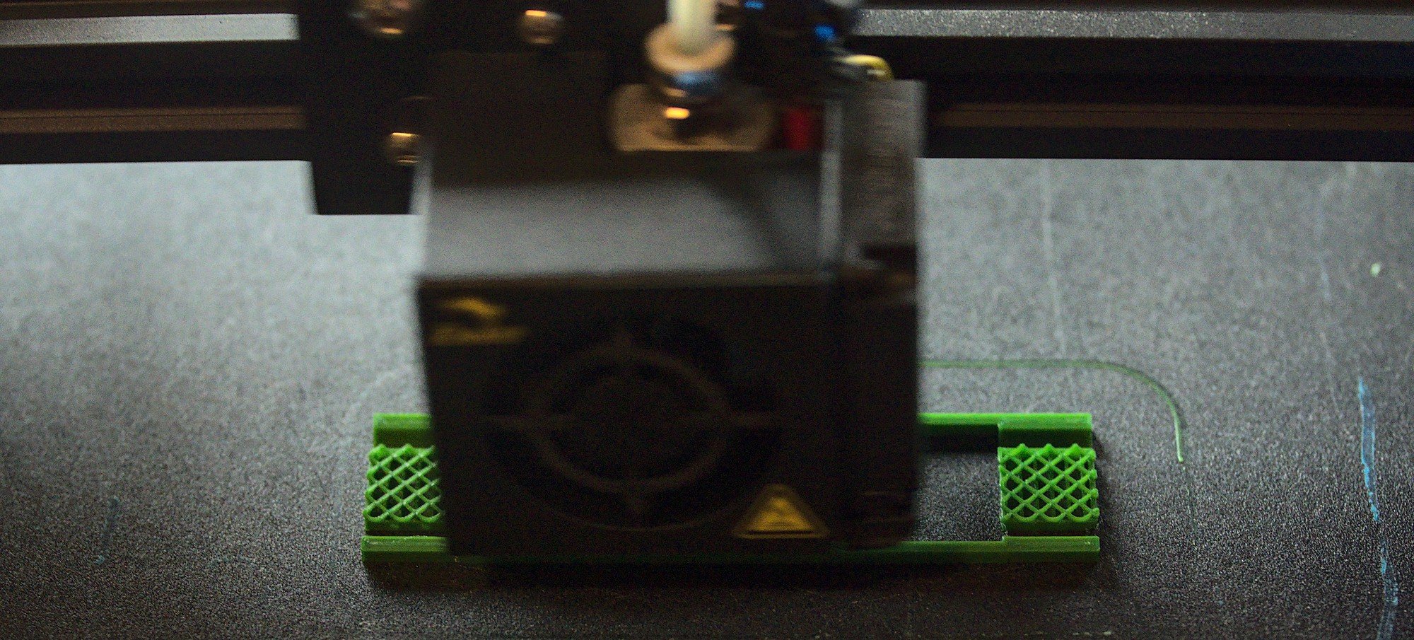
From this design I can generate an .stl file and send it to the 3D printer. The tray can print without any supports and takes about an hour on my printer. So 3 hours later I have the full base of the phone holder in my rack case.
To actually mount the phones there can be phone-specific models that grip into this baseplate and hold the phone and extra electronics. I made a somewhat generic phone mount that just needs two measurements entered to get the correct device thickness at two points. This is the holder I'm currently using for the PinePhone and the Oneplus 6.
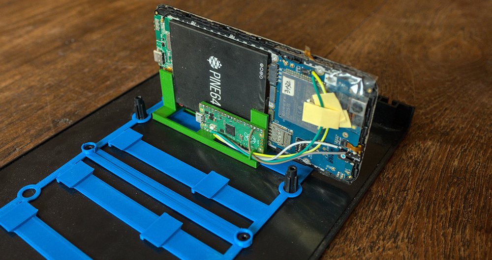
The baseplates here are in blue and the phone holder is the green print. This version of the phone holder is designed to hold the Raspberry Pi Pico and has a ring for managing the soldered cables to the device. The size of the PinePhone is about the largest this case can hold. It will fill up the full depth of the case when the USB-C cable is inserted and it also almost hits the top of the case.
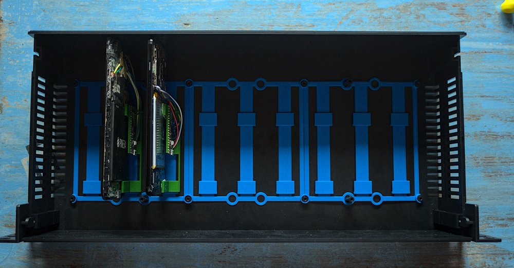
In this case I can hold 8 phones on the trays and have one of the slots on the tray left over to hold a future USB hub board that will have the 16 required USB ports to use all the devices in the case.
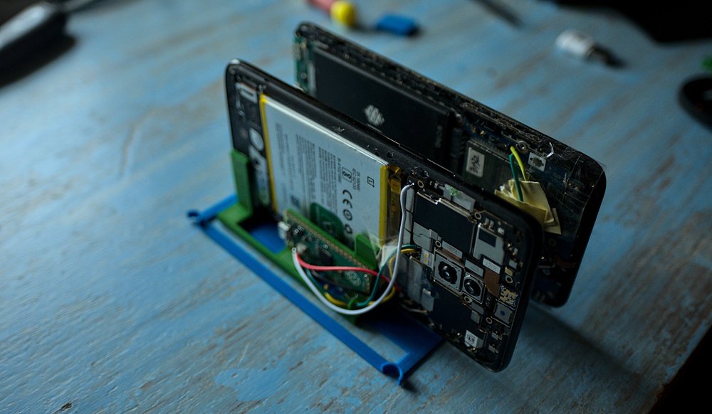
For small desk setups the a single tray is also pretty nice to hold devices and the phone holder itself will also stand on its own. This is great if you have one to three devices you want to hook up to your laptop for local development.
Running the first test job
So now the case is together and the controller is deployed it's time to run an actual test. For this first test I'll be using Jumpdrive as the test image. This is by far the smallest image available for the PinePhone which makes testing a lot easier. It just boots a minimal kernel and initramfs and the greatest feature for this test: it spawns a shell on the serial console.
Since GitHub is not a great hosting platform and the bandwidth limit for the https://github.com/dreemurrs-embedded/Jumpdrive repository has been reached it's not possible to fetch the raw file from github without being logged in so this script uses my own mirror of the latest PinePhone jumpdrive image.
devicetype: pine64-pinephone

boot {
  rootfs: http://brixitcdn.net/pine64-pinephone.img.xz
}

shell {
  prompt: / #
  success: Linux
  script {
    ip a
    uname -a
  }
}
This will boot Jumpdrive and then on the root console that's available over the serial port it will run ip a to show the networking info and then uname -a to get the kernel info. Because the success condition is Linux it will mark the job successful if the uname output is printed.
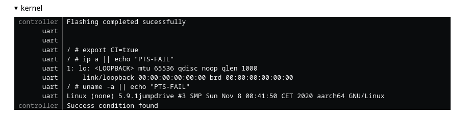
The serial output also shows another feature of the controller: it will set the environment before executing the script, which in this case is just the CI variable and it will add || echo "PTS-FAIL" to the commands so non-zero exit codes of the commands can be detected. When PTS-FAIL is in the serial output the task will be marked as failed. Using the success: and fail: variables in the script the success and failure text can be set.
With these building blocks for test scripts it's now possible to implement a wide variety of test cases. Due to Jumpdrive not having enough networking features enabled in the kernel it's not yet possible to upgrade from the serial connection to a telnet connection in the test setup, this would make the test cases a bit more reliable since there's a very real possibility that a few bits are flipped right in the success or failure string for the testjob marking a successful job as failed due to timeouts.
Getting a generic test initramfs to combine with a kernel to do basic testing will be a good thing to figure out for part 6, Jumpdrive only has busybox utilities available and only has very limited platform support in the first place.